Error-detection and error-correction techniques
The link layer can detect and sometimes correct bit errors in transmitted data.
Basic idea
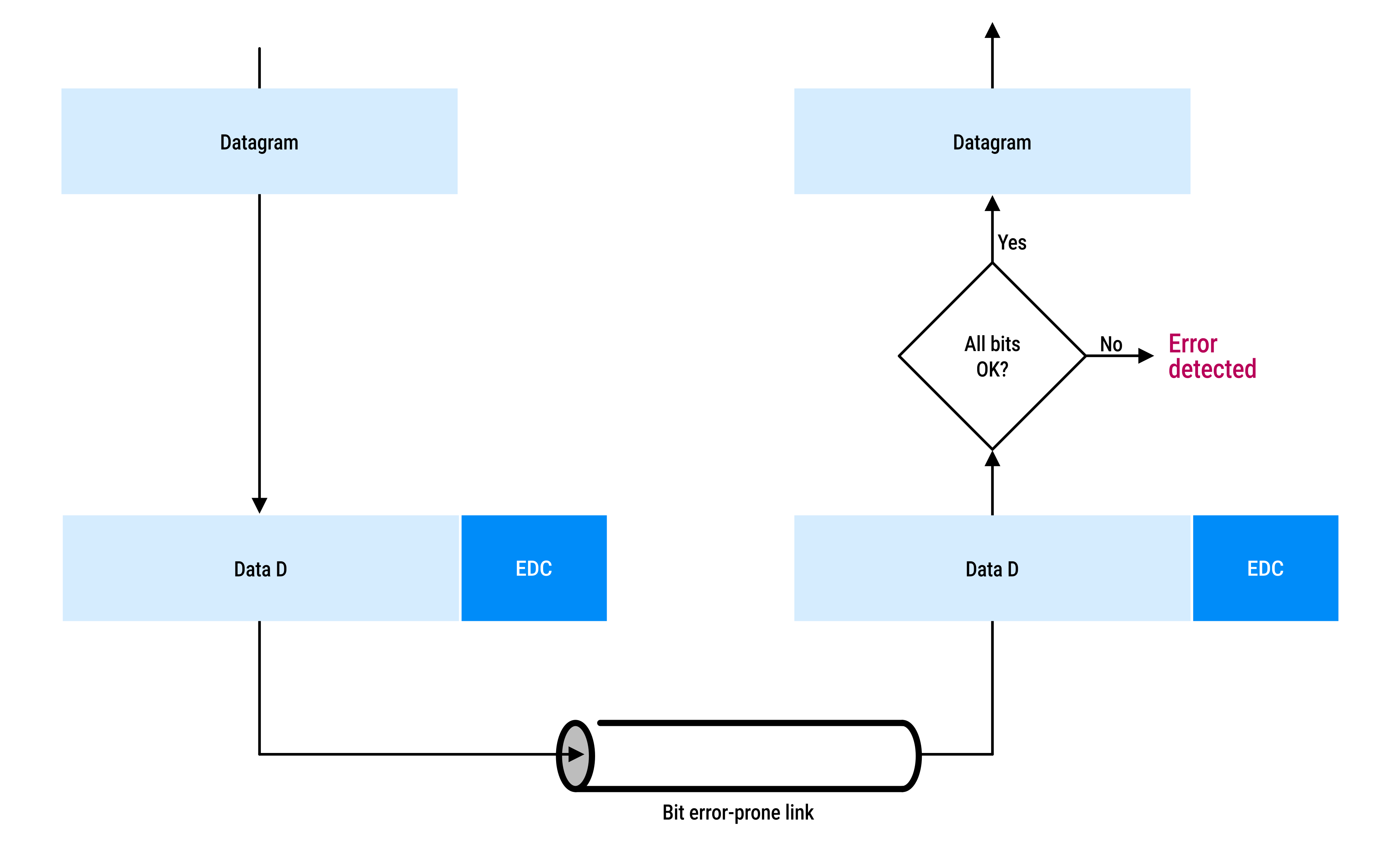
At the sender:
- the data
Dis prepared for transmission - the sender adds Error-Detection and -Correction (
EDC) bits toD - the resulting frame (
D + EDC) is sent to the receiver
At the receiver:
- the receiver gets
D + EDC, which may have been corrupted during transmission - it uses the
EDCbits to check whetherDis still valid - it attempts to detect errors, but:
- some bit errors may go undetected
- the receiver may not realize the data is incorrect
Common techniques used for error detection in transmitted data:
- Parity checks
- Checksumming
- Cyclic redundancy check (CRC)
More accurate error-detection methods reduce the chance of undetected errors, but they add more overhead (extra bits and processing).
Parity checks
Single parity bit
The simplest way to detect errors is to use a single parity bit.
If a message has d data bits, the sender adds a parity bit:
           d data bits         parity bit
                │                  │
                ↓                  ↓
┌───────────────────────────────┐┌───┐
│ 1 1 1 0 0 0 1 1 0 1 0 1 0 1 1 ││ 1 │
└───────────────────────────────┘└───┘
- even parity:
- the parity bit is chosen so the total number of
1s (data + parity bit) is even
- the parity bit is chosen so the total number of
- odd parity:
- the parity bit is chosen so the total number of
1s (data + parity bit) is odd
- the parity bit is chosen so the total number of
At the receiver:
- count the number of
1s in all received bits (d + 1) - with even parity:
- if the number of
1s is odd → an error is detected - if it is even → no error is detected (but errors may still exist)
- if the number of
Measurements have shown that:
- parity can miss some errors
- errors often happen in bursts, not individually
- in burst conditions, parity may fail to detect errors about half the time
- so, stronger error-detection methods are usually needed
Two-dimensional parity check
Two-dimensional parity check is an improved error detection method.
| Step | Explanations | Data | ||||||||||||||||||||||||||||||||
|---|---|---|---|---|---|---|---|---|---|---|---|---|---|---|---|---|---|---|---|---|---|---|---|---|---|---|---|---|---|---|---|---|---|---|
Step 1: arrange the data |
The data |
|
||||||||||||||||||||||||||||||||
Step 2: add parity bits |
Row parity: a parity bit is added at the end of each row. |
|
||||||||||||||||||||||||||||||||
|
Column parity: a final row of parity bits is added at the bottom. |
|
|||||||||||||||||||||||||||||||||
Step 3: transmission |
The sender transmits the full data ( |
|||||||||||||||||||||||||||||||||
Step 4: checking at the receiver |
The receiver rebuilds the same table and checks parity for every row and column. If all rows and columns have even parity, the data is assumed to be correct and the parity bits are removed. |
|
How is an error detected?
If a single bit changes during transmission:
- one row will fail the parity check
- one column will also fail the parity check
The intersection of the faulty row and column shows the exact bit that is wrong, allowing it to be corrected.
Two-dimensional parity can:
- detect single-bit errors
- correct single-bit errors
- detect (but not correct) any combination of two errors in a packet
This is called forward error correction (FEC). FEC techniques:
- reduces the need for retransmissions
- allows errors to be fixed immediately at the receiver
Checksumming
A common checksumming method is the Internet checksum (RFC 1071).
| Algorithm | 4-bit words example for simplicity | |
|---|---|---|
Sender |
1. treat the data as a sequence of 16-bit words |
|
2. add the words using 1's complement arithmetic (wrapping any carry back into the sum |
|
|
3. take the 1's complement of the final sum |
|
|
4. store the result in the segment header as the checksum |
|
|
Receiver |
1. add all of the received 16-bit words, including the checksum, using 1's complement arithmetic |
|
2. take the 1's complement of the result |
|
|
|
3. check whether the result is all 0 bits:
|
since the result is all |
Advantages:
- requires very little packet overhead (e.g. the checksums in TCP and UDP use only 16 bits)
- simple and fast to compute
Disadvantages:
- provides relatively weak protection against transmission errors
Checksumming is conceptually part of the transport layer and was designed to be implemented efficiently in software as part of the host operating system. For this reason, it uses a simple and fast error-detection technique.
Link-layer error detection can be implemented in dedicated network hardware (such as network adapters). Hardware can perform more complex error-detection algorithms efficiently, allowing stronger error protection than the simple transport-layer checksum.
Cyclic redundancy check (CRC)
A cyclic redundancy check (CRC) adds extra bits to data to detect errors during transmission.
CRC uses a special form of binary arithmetic known as polynomial arithmetic over GF(2) where:
- addition and subtraction are both performed using XOR
- there are no carries or borrows
The sender and receiver agree on a value G called the generator or generator polynomial.
Example for G = 1011:
Ghas 4 bits- degree of the polynomial = 3
- therefore
r = 3(number of zeros to append)
          Sender

  Data bits to be protected
┌───────────────────────────┐
│         D = 1101          │
└───────────────────────────┘
      append r zeros
             ↓
┌───────────────────────────┐
│    D followed by zeros    │
│         1101 000          │
└───────────────────────────┘
              ↓
┌───────────────────────────┐
│        Divide by G        │
│     (generator = 1011)    │
└───────────────────────────┘
             ↓
     Remainder R = 001

      Transmitted frame:
┌───────────────────────────┐
│      Data D       │   R   │
│       1101        │  001  │
└───────────────────────────┘
       D || R (concat)
The receiver divides the received message by the same G:
- if the remainder is 0, no transmission error is detected
- if the remainder is nonzero, an error has been detected
             Receiver

          Received frame:
   ┌───────────────────────────┐
   │      Data D       │   R   │
   │       1101        │  001  │
   └───────────────────────────┘
           D || R (concat)
                ↓
   ┌───────────────────────────┐
   │        Divide by G        │
   │     (generator = 1011)    │
   └───────────────────────────┘
                ↓

         Modulo-2 division

                  1101001
                  ÷  1011
          ---------------
          remainder = 000

                ↓
   ┌───────────────────────────┐
   │      Check remainder      │
   └───────────────────────────┘
                |
       ─────────────────────
      │                     │
      ↓                     ↓
┌───────────────┐ ┌───────────────┐
│ Remainder = 0 │ │ Remainder ≠ 0 │
│ No error      │ │ Error         │
│ Accept frame  │ │ Reject frame  │
└───────────────┘ └───────────────┘
CRC works by enforcing a divisibility property: the sender chooses R so that the transmitted frame D || R produces a zero remainder when divided by G using modulo-2 arithmetic.
CRC is an error-detection mechanism, not an error-correction mechanism.
 Joint
Joint