Multiplexing and demultiplexing
Multiplexing and demultiplexing are transport-layer mechanisms that enable extending host-to-host delivery to process-to-process delivery.
When data arrives at a host, the transport layer must route it to the correct process.
Sockets
The transport layer does not deliver data directly to a process.
Instead it delivers it to an intermediary software interface called a socket.
A process can have one or more sockets.
Multiplexing and demultiplexing
Multiplexing (muxing) = many-to-one at the sender:
- the transport layer gathers data from multiple sockets
- it adds a header to each piece of data, creating segments
- it sends the segments to the network layer
Demultiplexing (demuxing) = one-to-many at the receiver:
- the transport layer receives segments from the network layer
- it checks the header of each segment
- it routes the data to the correct socket (and thus the correct application process)
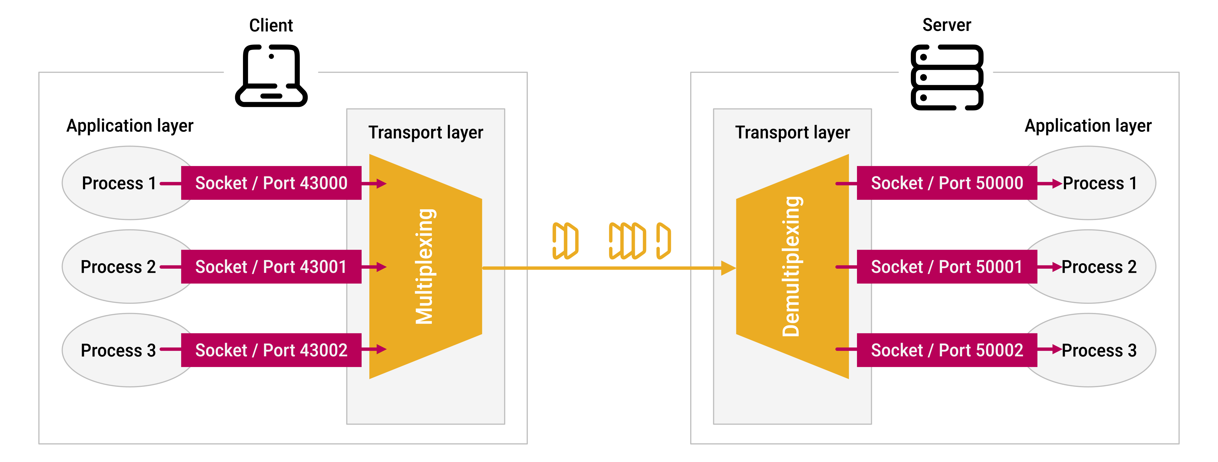
Household analogy
Multiplexing:
- letters from different family members are collected
- they are given to the mail carrier (many-to-one)
Demultiplexing:
- letters are received from the mail carrier
- the address on each letter is checked
- each letter is given to the correct family member (one-to-many)
Port numbers
This routing relies on port numbers:
-
each socket is assigned a port number, ranging from
0to65535:- port numbers
0to1023are called well-known port numbers and are restricted
- port numbers
-
port numbers are then embedded in each transport-layer segment's header:
- the source port number field
- the destination port number field
Demultiplexing in UDP and TCP
UDP
A server application creates a UDP socket and binds it to a local address:
(local IP, local port)
(192.168.1.2, 50000)
A client application creates a UDP socket:
(192.168.1.10, 43000)
When the client sends data to the server, the transport layer creates a UDP segment:
src port 43000
dst port 50000
The server host demultiplexes (directs) the UDP segment to the appropriate socket by examining the destination port number.
One server UDP socket can receive datagrams from many senders:
Sender A (192.168.1.10, 43000) → (192.168.1.2, 50000)
Sender B (192.168.1.11, 61000) → (192.168.1.2, 50000)
Sender C (192.168.1.12, 55000) → (192.168.1.2, 50000)
All of these datagrams are delivered to the same server socket because they have the same destination port number.
If needed, the receiving application can obtain the sender's address from the source IP address and source port.
TCP
A server application creates a TCP listening socket:
(local IP, local port)
(192.168.1.100, 50000)
A client application creates a TCP socket:
(192.168.1.10, 43000)
The client application initiates a TCP connection to the server.
When the server accepts the connection, the listening TCP socket creates a new socket dedicated to that client connection.
The new TCP connection socket is identified by a four-tuple:
(source IP, source port, destination IP, destination port)
(192.168.1.10, 43000, 192.168.1.100, 50000)
The original listening socket can accept more connections by creating dedicated new sockets:
  Listening socket
(192.168.1.100, 50000)
        |
        |
        +---- accept() ---- Client A connected socket
        |                  (192.168.1.10, 43000, 192.168.1.100, 50000)
        |
        +---- accept() ---- Client B connected socket
        |                  (192.168.1.11, 43001, 192.168.1.100, 50000)
        |
        +---- accept() ---- Client C connected socket
                           (192.168.1.12, 43002, 192.168.1.100, 50000)
The TCP layer demultiplexes (directs) each incoming TCP segment to the appropriate connection socket by examining the four values in the segment's connection identifier.
Summary
| UDP | TCP | |
|---|---|---|
| Server port | One socket is bound to it | One listening socket is bound to it |
| Client handling | Same socket handles all clients | New connection socket per client |
| Socket identity | Two-tuple | Four-tuple |
| Multiple clients on same server port? | Yes, same socket | Yes, different sockets |
 Joint
Joint