4G/5G cellular networks
4G and 5G are generations of cellular networks ("G" stands for generation.)
4G download speeds are around 20 Mbps or higher.
Specifications:
- Internet protocols are defined in RFCs
- 4G and 5G networks are defined in Technical Specifications
Cellular communications
The electromagnetic spectrum has only a limited number of channels, and many users compete for them.
Cellular communication solves this limitation by dividing coverage areas into smaller regions called cells:
- each cell has a base station (cell tower) that sends and receives signals from mobile devices within that area
- carriers place many antennas across the landscape so they can reuse the same frequencies in different nonadjacent cells
- cells are often represented as a idealized hexagonal grid, but their actual shape and size vary depending on real-world conditions
The coverage area of a cell depends on many factors:
- the transmitting power of the base station and mobile devices
- obstacles like buildings or mountains
- the height and type of the base station antennas
- the number of users and demand for service in the area
A cellular carrier (roughly opérateur in French) is a company that provides mobile phone service in a geographic area.
4G LTE: architecture
4G LTE networks implement the LTE (Long-Term Evolution) radio access technology standardized by 3GPP.
They are architecturally divided into two parts:
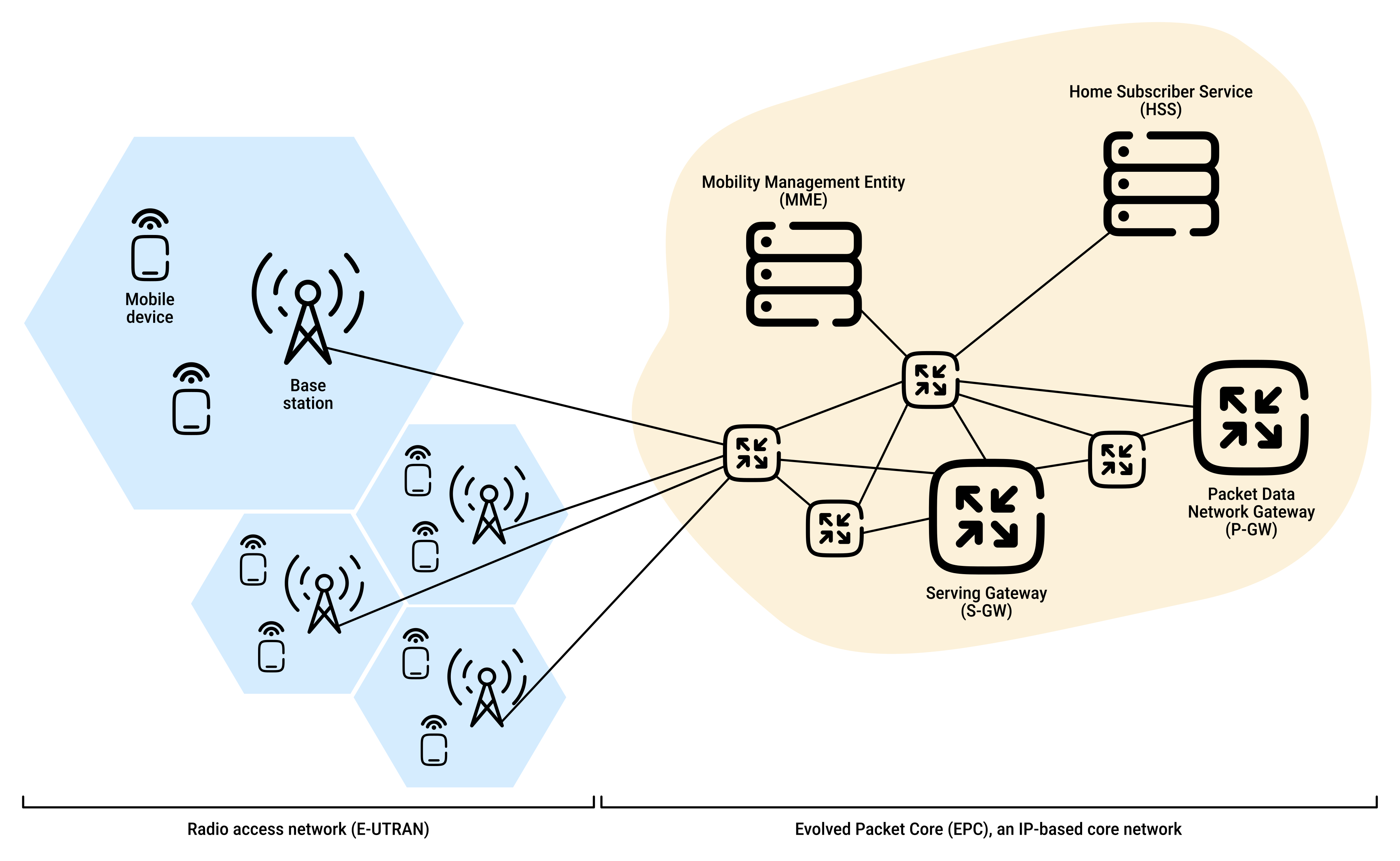
- the radio access network (E-UTRAN) at the cellular edge, which provides the radio link between mobile devices and base stations (the first hop into the network)
- the Evolved Packet Core (EPC), an IP-based core network that manages connectivity, mobility, authentication, and data routing between:
- the carrier's own network
- other carrier networks
- the Internet
4G LTE: elements
Major elements of the 4G LTE network architecture:
| Component | Description |
|---|---|
Mobile Device (UE - User Equipment) |
A device connecting to a cellular network (e.g., smartphone, tablet, laptop, IoT device) containing:
|
Cellular Base Station (eNode-B) |
The network edge element that manages devices and radio resources within its cell:
In LTE terminology, it is called eNode-B:
|
Home Subscriber Server (HSS) |
A control-plane database containing subscriber information for the carrier's home network. Used with the MME for device authentication. |
Gateway Routers (S-GW and P-GW) |
Serving Gateway (S-GW):
Packet Data Network Gateway (P-GW):
|
Mobility Management Entity (MME) |
A control-plane element responsible for authentication, mobility, and tunnel management:
|
4G LTE: tunnels
The data path from the mobile device to the carrier gateway consists of:
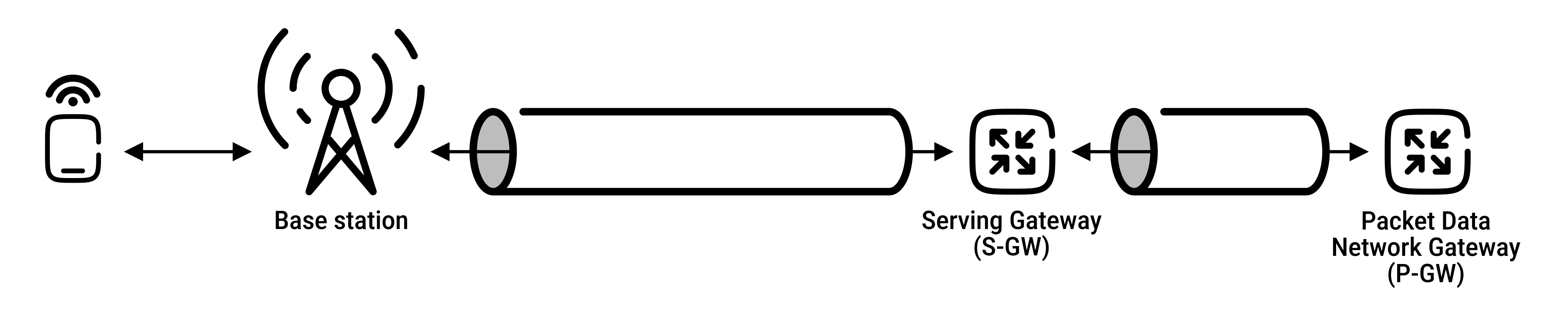
- a wireless first hop between the mobile device and base station (UE ↔ eNode-B)
- concatenated IP tunnels:
- between the base station and S-GW (eNode-B ↔ S-GW)
- between the S-GW and P-GW (S-GW ↔ P-GW)
Tunnels are established under MME control when the mobile device first attaches to the network:
- each tunnel endpoint is identified by a Tunnel Endpoint Identifier (TEID)
- when the base station receives datagrams from the mobile device:
- it encapsulates them using the GPRS Tunneling Protocol including the TEID
- and sends them in UDP segments to the Serving Gateway (at the other end of the tunnel)
When a device moves:
- only the tunnel between the base station and S-GW changes
- other tunnel endpoints and their Quality of Service (QoS) settings remain unchanged
LTE protocols stacks
Since 4G LTE is an all-IP architecture:
- many of its protocols are already familiar: IP, TCP, UDP, and application layer protocols
- but there are also specific protocols:
- at the link layer
- at the physical layer
- in mobility management
LTE data-plane protocol stacks at the mobile node, the base station and the serving gateway:
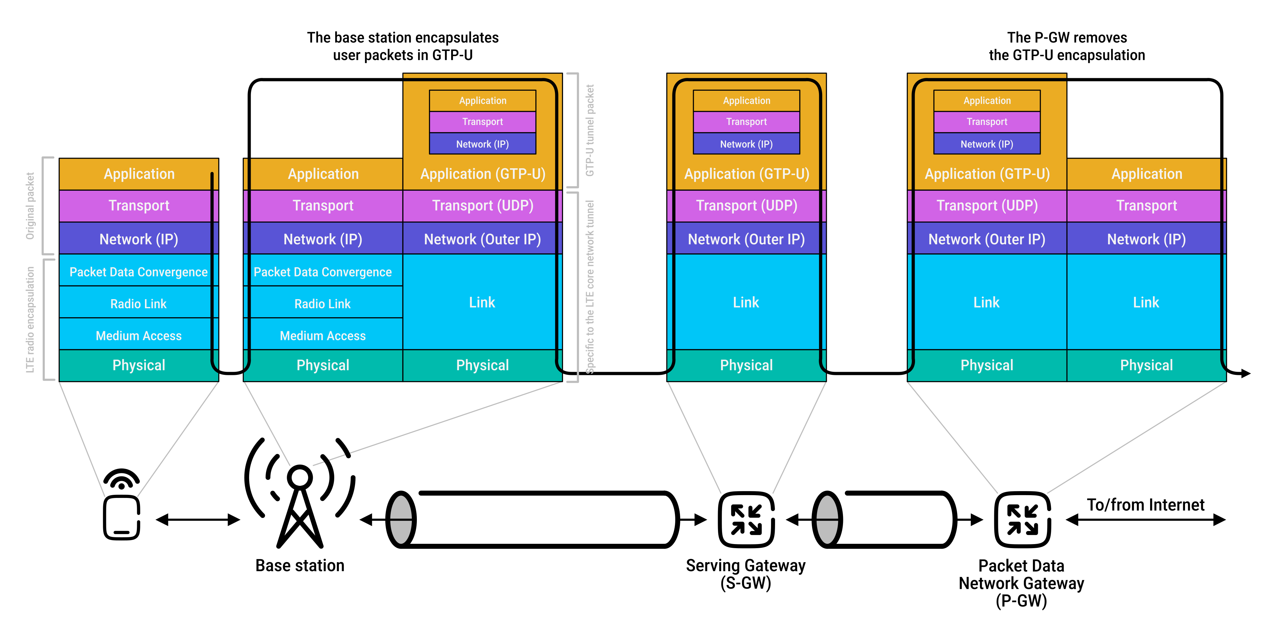
Most LTE-specific data-plane protocol activity occurs on the wireless link between the mobile device and the base station
The link layer on the mobile device is divided into three sublayers:
- Packet Data Convergence Protocol (PDCP)
- sits just below IP
- compresses IP headers to reduce transmitted data
- encrypts and decrypts IP datagrams
- Radio Link Control (RLC) Protocol
- splits large IP datagrams into smaller pieces for transmission and reassembles them at the receiver
- provides link-layer reliable delivery using an ACK/NAK-based ARQ protocol
- Medium Access Control (MAC)
- coordinates access to radio resources through scheduling
LTE radio resource allocation
LTE uses Orthogonal Frequency Division Multiplexing (OFDM) on the downlink, which combines:
- frequency division multiplexing (FDM)
- time division multiplexing
Orthogonal means the signals on closely spaced frequency channels are designed to interfere very little with each other.
Each active mobile device is allocated:
- one or more 0.5 ms time slots
- on one or more frequency channels
Allocating more time slots (whether on the same or on different frequencies) increases the device's data rate.
The network can:
- reassign time slots as often as every 1 ms
- adjust the modulation scheme to change transmission speed
LTE scheduling
The LTE standard does not specify how time slots are assigned.
Instead, scheduling decisions (such as which device transmits on which frequency and at what time) are made by algorithms implemented by the LTE equipment vendor and/or network operator.
A common scheduling strategy is opportunistic scheduling, in which the base station makes efficient use of the wireless medium by:
- adapting transmissions to current wireless channel conditions
- selecting users with the best channel quality for transmission
Scheduling decisions can also consider:
- user priority
- contracted levels of service (e.g., silver, gold, or platinum)
LTE network attachment
When a mobile device connects to an LTE network, the process happens in three phases:
| Step | Description |
|---|---|
|
1. Attachment to a base station |
|
|
2. Mutual authentication |
|
|
3. Data path configuration |
|
LTE power management
LTE devices use sleep modes to reduce battery consumption while maintaining connectivity.
A sleeping LTE device can be in two states:
- discontinuous reception state:
- entered after a few hundred milliseconds of inactivity
- the mobile device and base station schedule regular wake-up times
- during these times, the device monitors the channel for downstream (base station to mobile device) transmissions
- between wake-up periods, the device radio is turned off to save power
- idle state:
- entered after a longer period of inactivity
- the device releases its active radio connection and wakes up less frequently to monitor the network
- when it wakes up, it may need to reconnect with a base station, especially if it has moved to a new area
The global cellular network: a network of networks
The global cellular network is a network of networks, similar to the Internet:
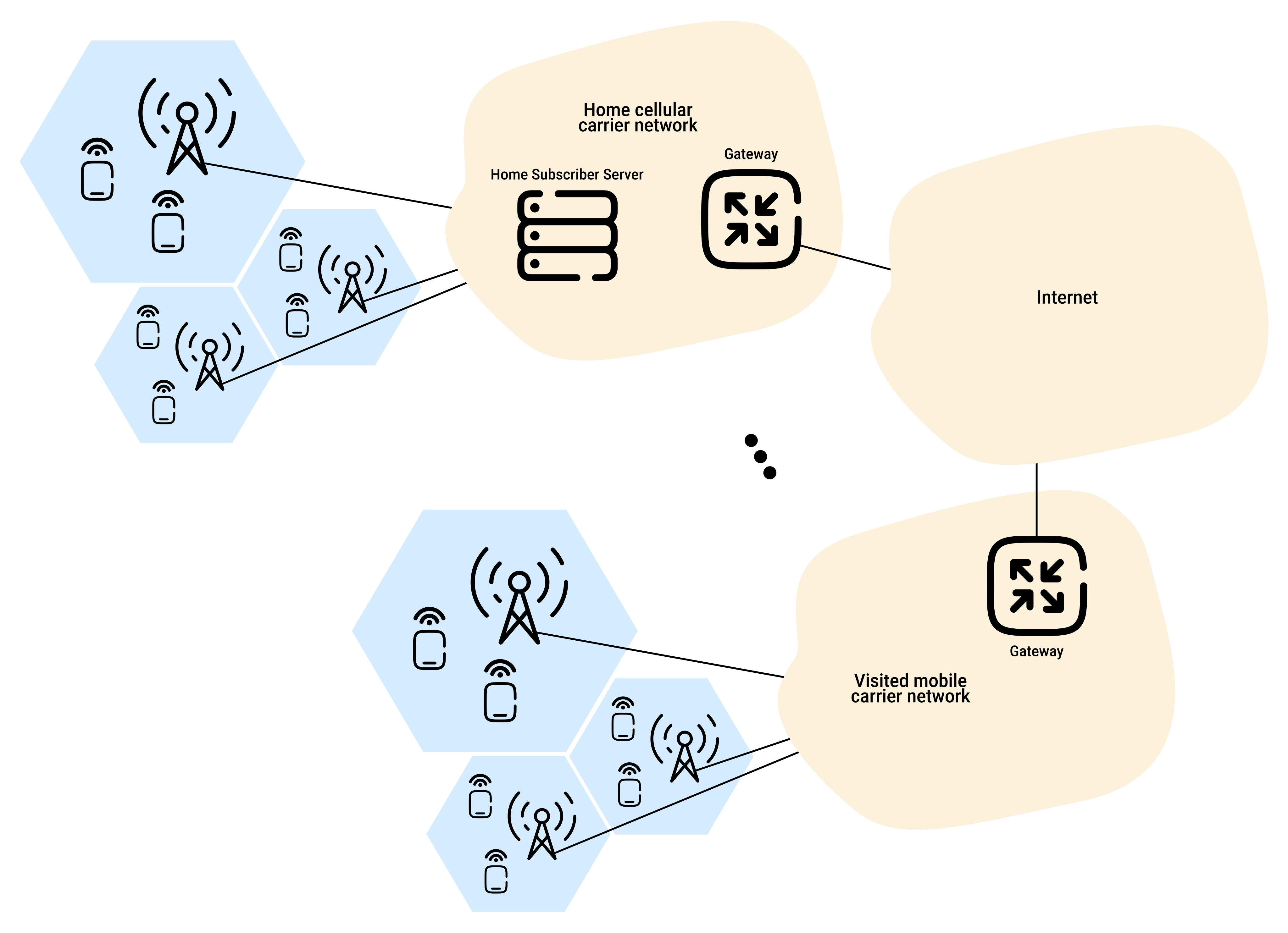
- a smartphone connects to a base station, which connects it to the user's home network
- the home network is operated by a cellular carrier
- the home network connects to:
- other cellular carrier networks
- the global Internet
- mobile networks interconnect with each other using:
- gateway routers
- private carrier networks such as IPX (especially for services like international roaming)
5G cellular networks
5G usually refers to 5G NR (New Radio), the radio access technology standardized by 3GPP.
The 5G NR air interface is not backward-compatible with 4G LTE, meaning carriers must invest heavily in new infrastructure during the transition.
5G network design focuses on three major service categories:
- eMBB (Enhanced Mobile Broadband):
- provides higher bandwidth and faster data rates
- supports peak rates up to 10 Gbps under ideal conditions
- enables applications such as HD video streaming
- URLLC (Ultra Reliable Low-Latency Communications):
- targets extremely low latency (around 1 millisecond)
- ideal for mission-critical latency-sensitive applications such as factory automation and autonomous vehicles
- mMTC (Massive Machine Type Communications):
- targets large numbers of low-power connected devices
- enables applications such as sensing, metering, and monitoring in IoT environments
5G frequencies
5G frequencies are divided into two groups:
- FR1 (410 MHz–7.125 GHz)
- most early deployments use FR1 frequencies
- FR2 (24.25 GHz–52.6 GHz)
- also known as millimeter wave (mmWave) frequencies
- enables much higher data speeds because it supports wider channel bandwidths
However, FR2 has two major limitations:
- shorter range:
- requires denser deployments of base stations in urban areas
- generally unsuitable for rural areas
- greater sensitivity to interference:
- rain, foliage, buildings, and other environmental factors can significantly reduce signal strength
5G millimeter wave frequencies
Many of the highest-capacity 5G deployments rely on millimeter wave frequencies in the 24–52 GHz range.
These frequencies can potentially increase network capacity by up to 100 times compared with 4G.
Network capacity can be described as:
capacity = cell density × available spectrum × spectral efficiency
Where:
cell density= number of cells per km²available spectrum= amount of frequency bandwidth available (Hz)spectral efficiency= how efficiently a cell uses its available frequency to communicate with users (bps/Hz/cell)
Multiplying these units gives a capacity in bps/km2.
In 5G, all three factors increase compared with 4G:
| Factor | Explanation |
|---|---|
Higher cell density |
|
More available spectrum |
|
Higher spectral efficiency |
|
By increasing all three terms in the capacity equation, 5G can achieve up to a 100× increase in capacity in dense urban areas.
The wider frequency bands also allow peak download speeds of 1 Gbps or more.
However, millimeter wave signals have limited range because they are easily blocked by obstacles such as buildings and trees. To maintain reliable coverage, 5G networks need many small cells to fill gaps between users and larger base stations. In densely populated areas, these small cells may need to be deployed only tens to hundreds of meters apart.
5G core network
The 5G Core network is the central part of the 5G system responsible for managing connectivity, mobility, authentication, policy control, and data services. It supports services such as mobile Internet access and voice services.
Compared with 4G, the 5G Core:
- is built around Control Plane and User Plane Separation (CUPS)
- uses software-based, cloud-native network functions
The control plane vs data plane distinction at the network layer and CUPS in 5G Core are based on the same principle:
- control plane = makes decisions, maintains network state, and manages connections
- user/data plane = forwards user traffic according to those decisions
The 5G Core decomposes the 4G MME into two elements:
- Access and Mobility Management Function (AMF)
- manages device registration, access, and mobility
- handles signaling between the device and the core network
- Session Management Function (SMF)
- manages user sessions
- communicates with the UPF to control user traffic
- manages IP address allocation and session policies
 Joint
Joint