VLANs
LANs drawbacks
A traditional switched LAN has three main drawbacks:
| Drawback | Explanation |
|---|---|
|
1. No traffic isolation |
Broadcast traffic (such as ARP requests and DHCP discovery messages) is sent throughout the entire network. Limiting the scope of broadcast traffic would improve:
|
|
2. Inefficient use of switches |
Suppose there are 10 departments:
|
|
3. Difficult user management |
If an employee changes departments: the physical network cable must be moved to another switch. If an employee belongs to multiple groups, the problem becomes even more complicated. |
Each of these difficulties can be handled by a switch that supports virtual local area networks (VLANs).
What is a VLAN?
A Virtual Local Area Network (VLAN) allows multiple logical LANs to share the same physical switch.
In a port-based VLAN, the network administrator assigns switch ports to VLANs.
Each VLAN forms its own broadcast domain, meaning:
- broadcast frames stay within that VLAN
- devices in different VLANs cannot directly communicate at Layer 2
For example, on a 16-port switch:
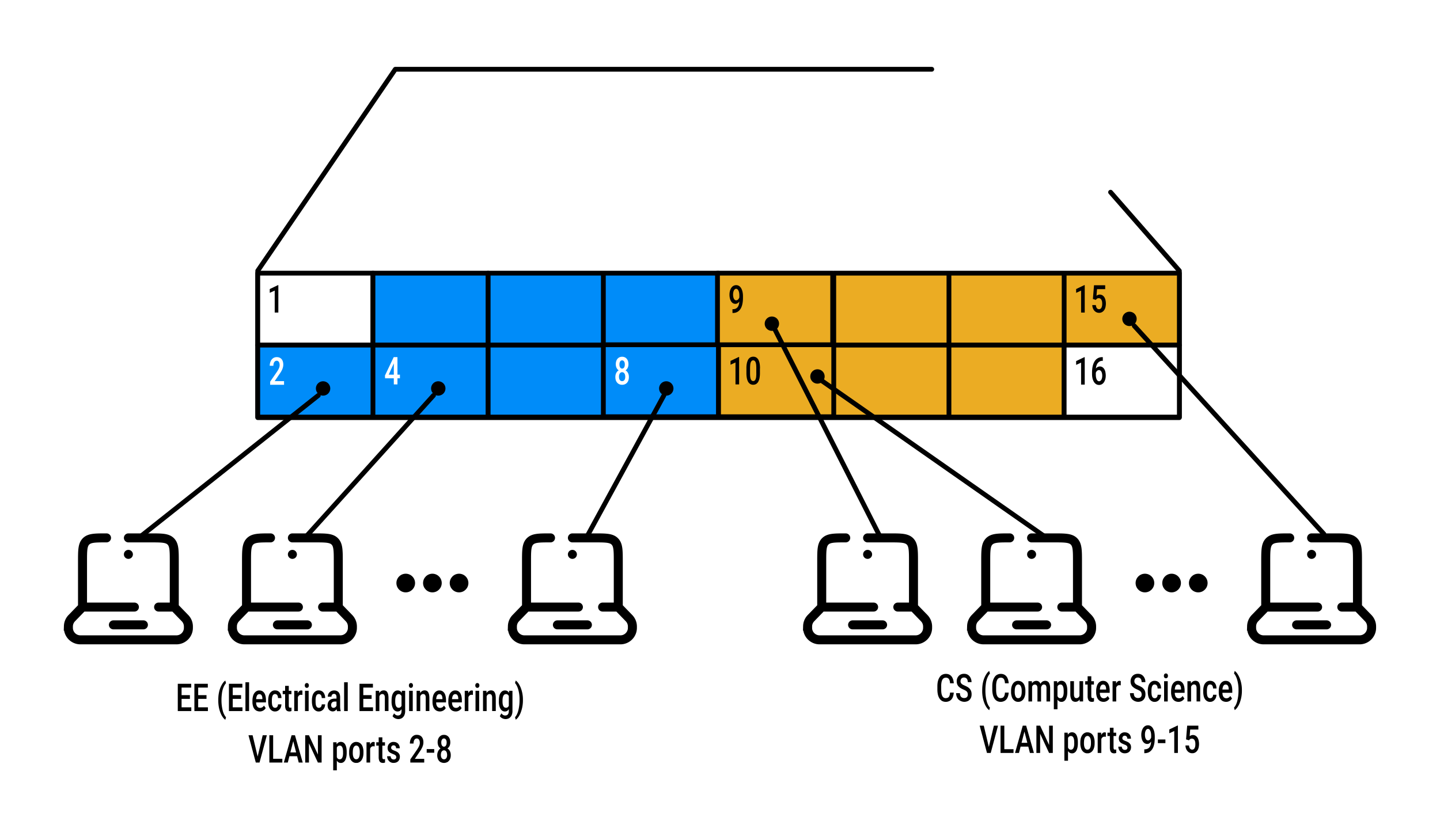
- ports 2–8 belong to the EE VLAN
- ports 9–15 belong to the CS VLAN
- ports 1 and 16 are unassigned (they remain in the default VLAN)
This VLAN provides several benefits:
- EE and CS traffic is isolated
- one physical switch replaces two separate switches
- if the user connected to port 8 joins the CS department, the administrator simply reassigns port 8 to the CS VLAN (no rewiring is required)
Communication between VLANs
Complete isolation introduces a new problem: how can devices in the EE VLAN communicate with devices in the CS VLAN?
The traditional solution is to connect the VLAN switch to a router:
- connect a VLAN switch port to an external router
- configure the router interface using subinterfaces, each associated with a VLAN (one for EE and one for CS)
- traffic from the EE VLAN is sent to the router
- the router routes the traffic and forwards it back onto the appropriate VLAN
Logically, this is equivalent to having two separate switches connected by a router.
Today, most enterprise switches include both switching and routing functionality, so a separate external router is usually unnecessary.
VLANs across multiple switches
Suppose some EE and CS hosts are located in a different building but should still belong to their department's VLAN.
A second 8-port switch can be used where the switch ports are defined as belonging to the EE or the CS VLAN:
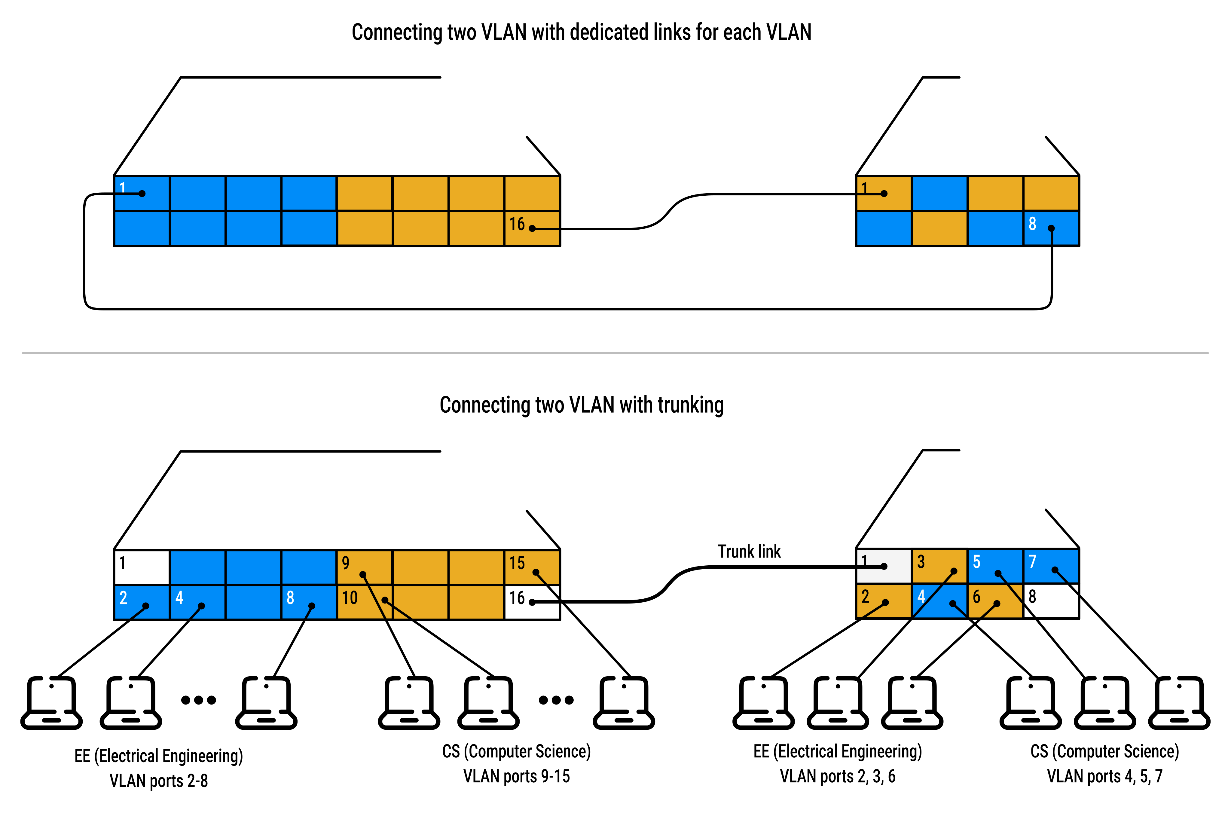
How should the two switches be interconnected?
Solution (a): dedicated links for each VLAN
- dedicate one port on each switch to the CS VLAN and connect them together
- dedicate another pair of ports for the EE VLAN
- repeat this for every VLAN
This approach does not scale: N VLANS would require N ports on each switch.
Solution (b): VLAN trunking:
- a more scalable solution is VLAN trunking
- instead of using one link per VLAN, a special port on each switch is configured as a "trunk port"
- the trunk ports interconnect the two VLAN switches:
- left switch: port 16
- right switch: port 1
- the trunk carries traffic for all VLANs
How does a switch know that a frame crossing a VLAN trunk belongs to a particular VLAN?
The IEEE 802.1Q standard extends the Ethernet frame by adding a 4-byte VLAN tag into the header:
- it contains the VLAN identifier, allowing switches to determine which VLAN the frame belongs to
- it's added by the switch at the sending side of a VLAN trunk
- it's parsed and removed by the switch at the receiving side of the trunk
Other ways to define VLANs
Although port-based VLANs are the most common, VLANs can also be defined in other ways.
- MAC-based VLANs:
- the administrator specifies the set of MAC addresses that belong to each VLAN
- whenever a device connects, the switch automatically places it into the appropriate VLAN based on its MAC address
- protocol-based VLANs:
- devices are grouped according to the network-layer protocol they use (IPv4, IPv6, AppleTalk, etc.)
- VLANs across routers:
- technologies (for example, VXLAN or MPLS Layer-2 VPNs) can be used to extend a VLAN across an IP network
- allowing geographically separated LANs to appear as part of the same logical VLAN
- this requires additional mechanisms beyond normal IP routing (for example, Layer-2 tunneling or overlay technologies)
 Joint
Joint