Router
High-level view of a generic router architecture:
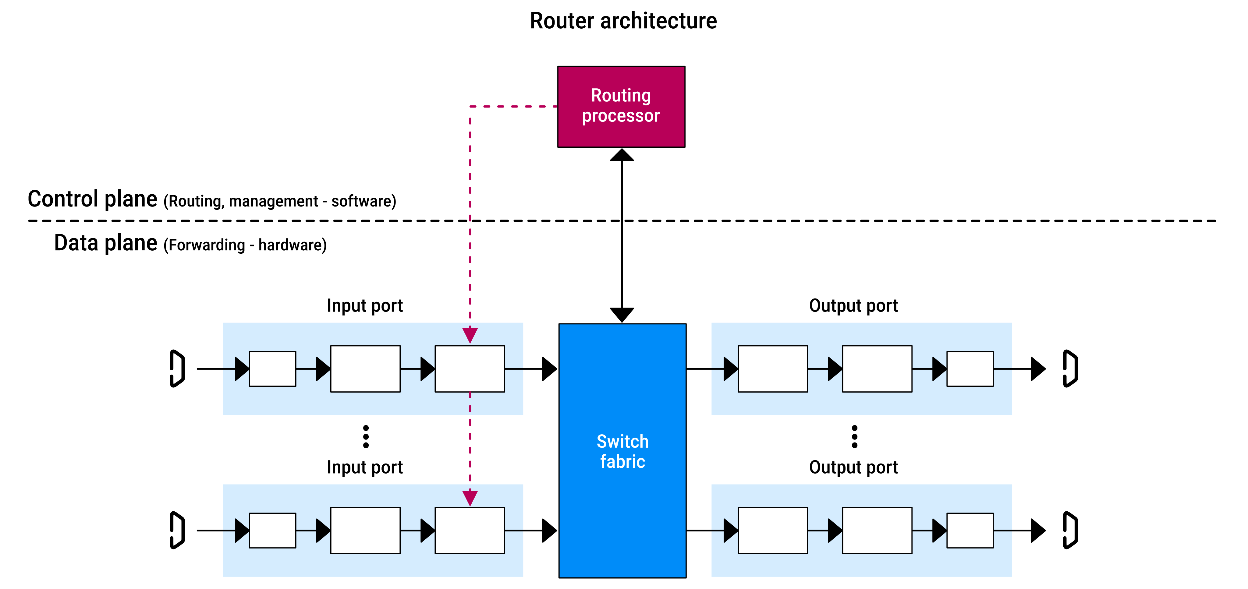
| Component | Details |
|---|---|
Input ports |
|
Switching fabric |
|
Output ports |
|
Routing processor |
|
Why hardware is used?
Input ports, output ports, and switching fabric are almost always hardware-based because processing must be extremely fast.
Example:
- a
64-byteIP datagram =512 bits - a 100 Gbps link =
10^11 bits/sec - at this speed, packets can arrive about every
5.12 ns- because
512 / 10^11 = 5.12e-9 - (divide the file size by the transfer time)
- because
- that means the router's input port must make a forwarding decision in a few nanoseconds per packet, or it will fall behind
- if a router has
Ninput ports, it must handle multiple such high-speed streams in parallel - this is why routers use specialized hardware: software cannot process packets at this speed
Destination-based forwarding
Each input port uses the forwarding table to determine which output port should receive the packet.
The forwarding table is created and updated by either:
- the router's routing processor
- a remote SDN controller
In the simplest form of forwarding, the output port is chosen solely based on the packet's destination IP address.
Creating a forwarding table entry for every possible IP address is impractical because IPv4 has about 4 billion possible addresses.
Instead packets are forwarded based on ranges.
E.g., for a router with four links, numbered 0 through 3:
| Prefix | Link Interface |
|---|---|
11001000 00010111 00010 |
0 |
11001000 00010111 00011000 |
1 |
11001000 00010111 00011 |
2 |
| Otherwise | 3 |
The router compares the destination address with the prefixes in the table.
A destination address may match multiple entries:
- e.g.
11001000 00010111 00011000 10101010matches both:11001000 00010111 00011000(first 24 bits) → entry111001000 00010111 00011(first 21 bits) → entry2
- in this case the router uses the longest prefix matching rule, choosing the most specific match
Lookup is conceptually simple with a forwarding table:
- but at transmission rates of hundreds of gigabits per second, this lookup must be performed in nanoseconds
- so not only must lookup be performed in hardware
- but techniques beyond a simple linear search through a large table are needed
- special attention must also be paid to memory access times
- in practice (on-chip) Ternary Content Addressable Memories (TCAMs) are often used for lookup
Sending the packet through the switching fabric
After the output port is identified, the packet is sent through the switching fabric.
If the switching fabric is busy, a packet may be temporarily blocked from entering it.
The blocked packet will be queued at the input port and scheduled to cross the fabric later.
Match + action
The input port's forwarding process consists of:
- match: find the forwarding-table entry that matches the destination address
- action: send the packet into the switching fabric to the specified output port
This match + action is a pattern widely used in networking devices, not just routers.
Switching
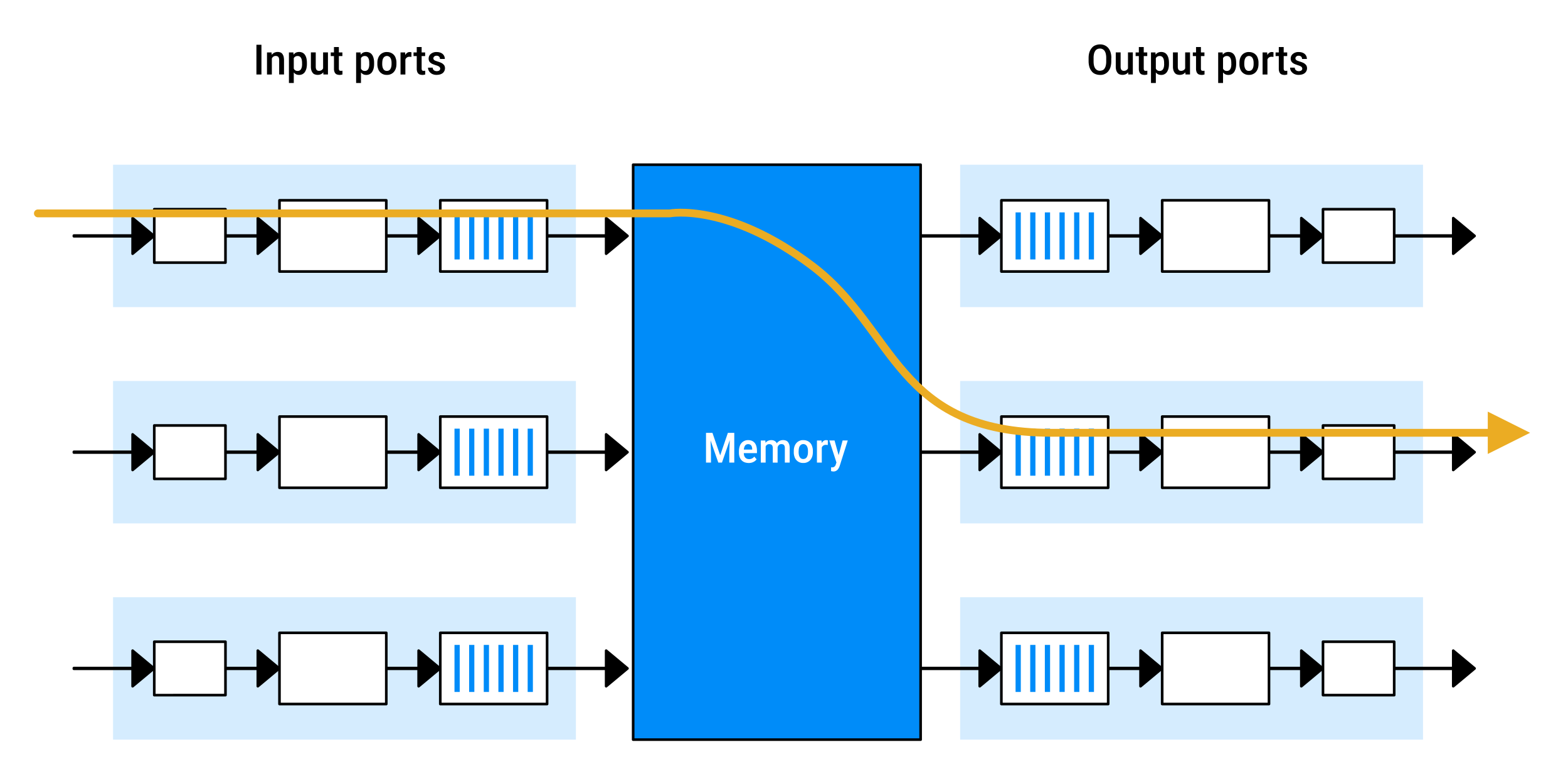
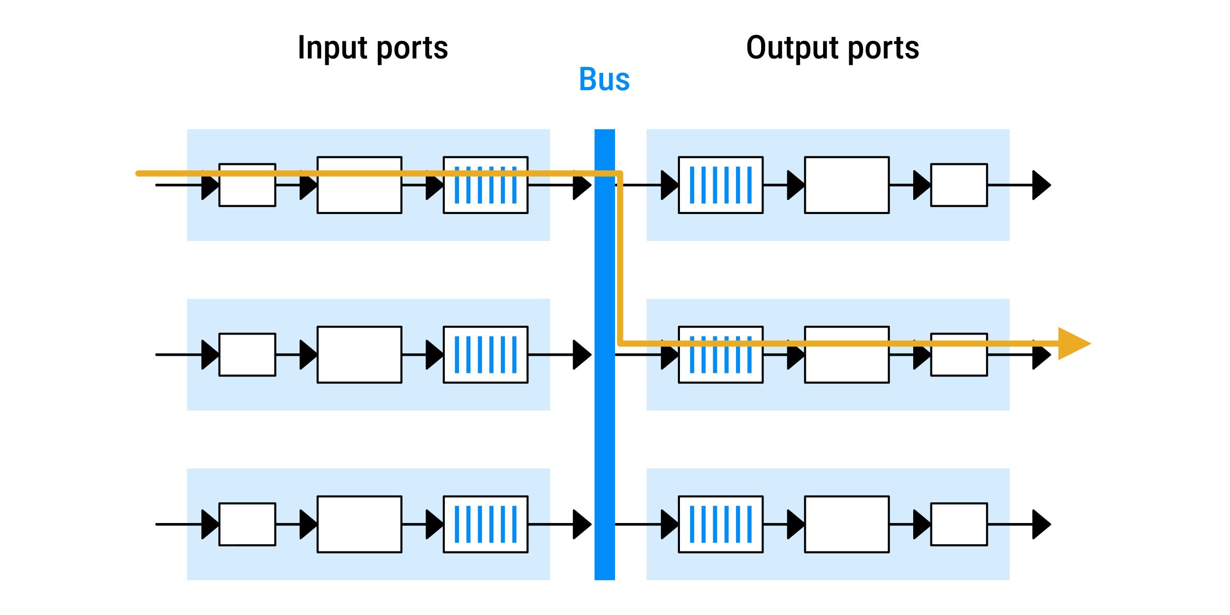
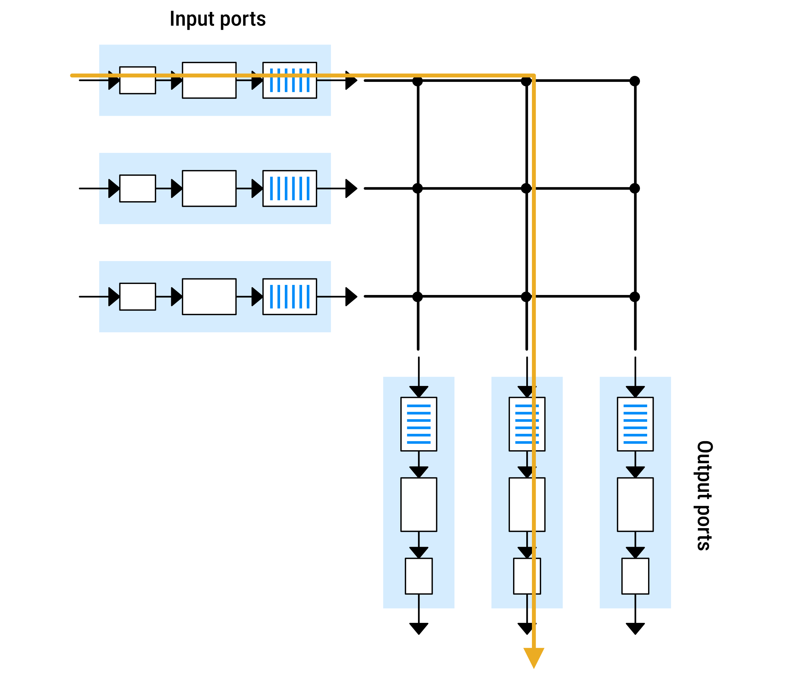
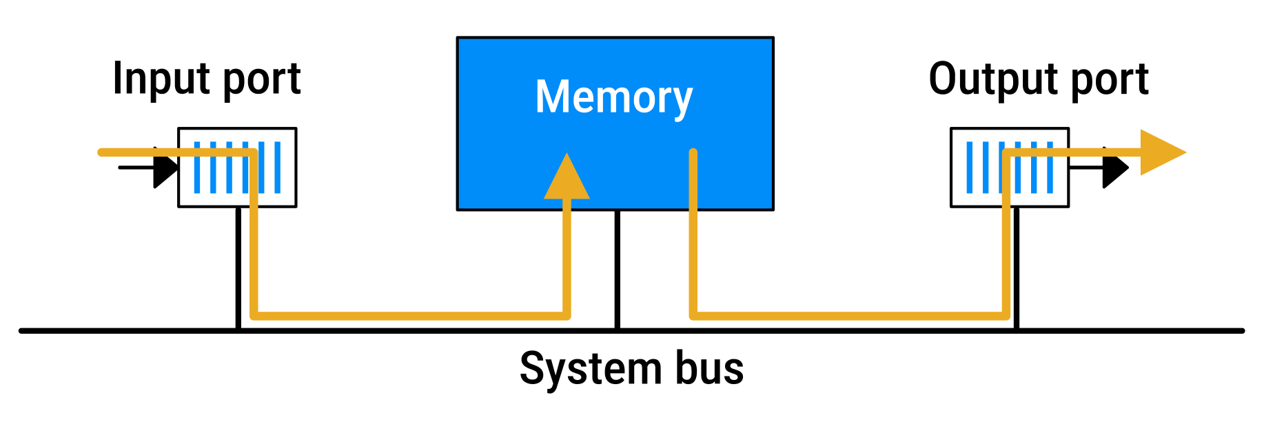
The switching fabric is the part of a router that moves packets from an input port to the correct output port.
The main performance measure is the switching rate (how fast packets can be forwarded).
There are three types of switching fabrics:
| Switching Method | Details | Diagram |
|---|---|---|
|
Switching via memory |
|
|
|
Switching via a bus |
|
|
|
Switching via an interconnection (crossbar) network |
|
|
Queuing
Packet queues may form at both the input ports and the output ports.
It is here, at these queues within a router, that packets are actually dropped and lost.
As these queues grow large:
- the router's memory can eventually be exhausted
- and packet loss will occur when no memory is available to store arriving packets
Input Queuing
Head-of-line (HOL) blocking occurs when the packet at the front of an input queue cannot be sent because its desired output port is busy.
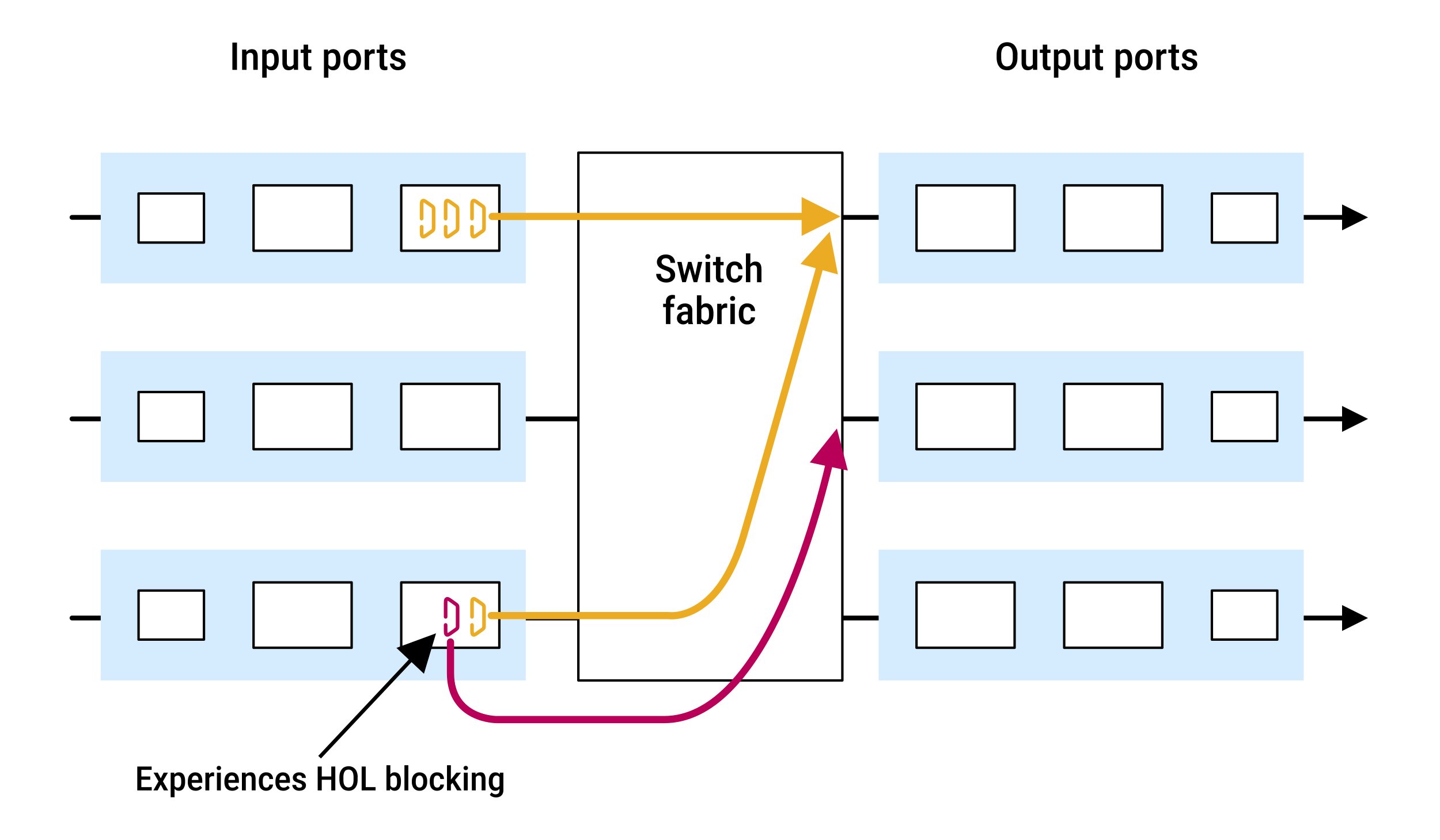
- the packet at the front of the upper-left input queue and the packet at the front of the lower-left input queue both want to use the upper-right output port
- the switch forwards the packet from the upper-left input queue first
- the packet at the front of the lower-left input queue must therefore wait
- because the queue is FIFO, all packets behind it must also wait
- some of those waiting packets may be destined for the middle-right output port, which is available, but they still cannot move forward
Result:
- one blocked packet can stall an entire queue
- this reduces overall switch performance
- when load gets high (around ~58% under certain assumptions), queue lengths can grow rapidly, leading to heavy delay and possible packet loss
Possible solutions:
- use shared memory rather than FIFOs for the input buffers
- buffer packets at output ports instead of input ports
Trade-offs:
- shared memory is expensive
- output buffering requires a faster switching fabric than the output links
Therefore, cheap devices usually don't have these features.
Output queuing
Output queuing occurs when packets arrive at an output port faster than the output link can transmit them.
This can happen when multiple input ports send packets to the same output port at the same time.
The excess packets are stored in an output queue, which may continue to grow if arrivals exceed the transmission rate.
When there is not enough memory to buffer a packet, a decision must be made:
- drop the arriving packet (a policy known as drop-tail)
- or remove one or more already-queued packets to make room for the newly arrived packet
In some cases:
- it may be advantageous to drop (or mark the header of) a packet before the buffer is full in order to provide a congestion signal to the sender
- this marking could be done using the Explicit Congestion Notification bits
- proactive packet-dropping and packet-marking policies:
- are collectively known as active queue management (AQM) algorithms
- one of the most widely implemented AQM algorithms is the Random Early Detection (RED) algorithm
Because multiple packets may be queued, the output port must use a scheduling policy to decide which packet to transmit next.
How much buffering is enough?
Larger buffers are not always better.
Rules
Traditionally, a common guideline was that buffer size should be approximately the bandwidth-delay product:
B = RTT × CB= buffer sizeRTT= average round-trip timeC= link capacity
- example:
RTT = 250 msecC = 10-GbpsB = 250 msec × 10-Gbps = 2.5 Gbits
This guideline was derived from analyses of TCP behaviour with a relatively small number of TCP flows.
Later research showed that when many TCP flows share a bottleneck link, their traffic fluctuations tend to average out, so much smaller buffers can often maintain high throughput:
B = RTT × C / √NN= number of concurrent TCP flows
In the network core, N can be large (routers carry thousands of flows), so the required buffer size can be much smaller than the bandwidth-delay product.
Larger buffers can absorb bursts and reduce packet loss, but they also increase queueing delay. Buffer sizing is therefore a trade-off between maintaining high throughput and keeping latency low.
Bufferbloat
Bufferbloat happens when a network device has a buffer that is so large that packets spend a long time waiting in line instead of being sent or dropped:
- packets arrive faster than they can leave
- the router stores them in its buffer
- the buffer becomes a long waiting line
- packets experience increased delay
Excessive buffering can create persistent latency even when a single application is using the connection and no other traffic is competing for bandwidth.
Users often perceive this as a slow or unresponsive network despite having plenty of bandwidth.
Packet scheduling
Packet scheduling refers to the process of deciding the order in which packets are transmitted over an outgoing link.
| Queuing discipline | Description | Diagram |
|---|---|---|
First-in-First-Out (FIFO) |
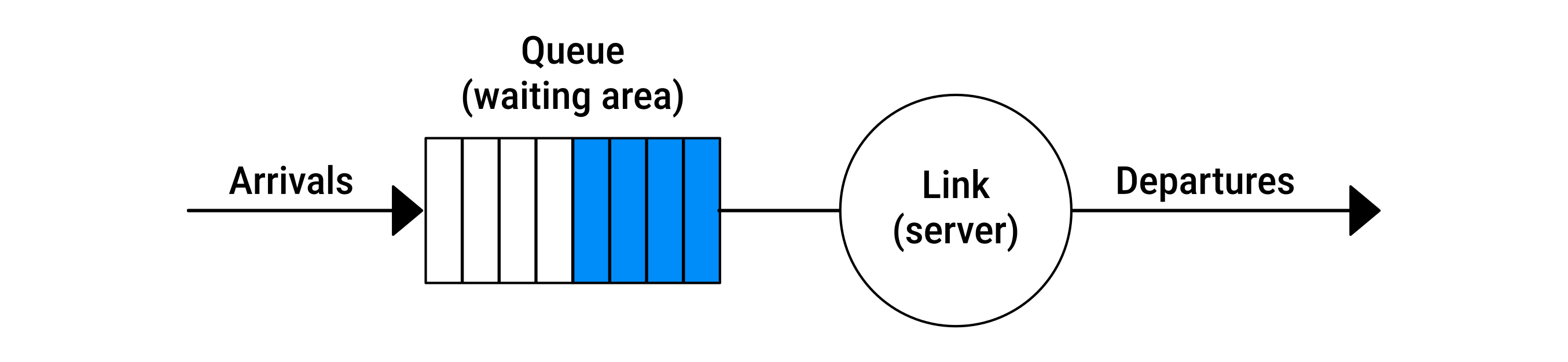
Also known as First-Come, First-Served (FCFS), FIFO transmits packets in the same order they arrive. If the buffer is full, the queue's drop policy determines whether:
|
|
Priority queuing |
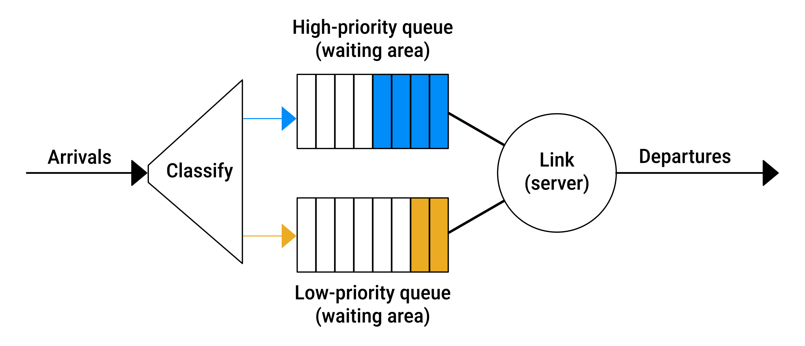
Packets are classified into priority levels when they arrive at the queue. In practice:
Transmission rules:
|
|
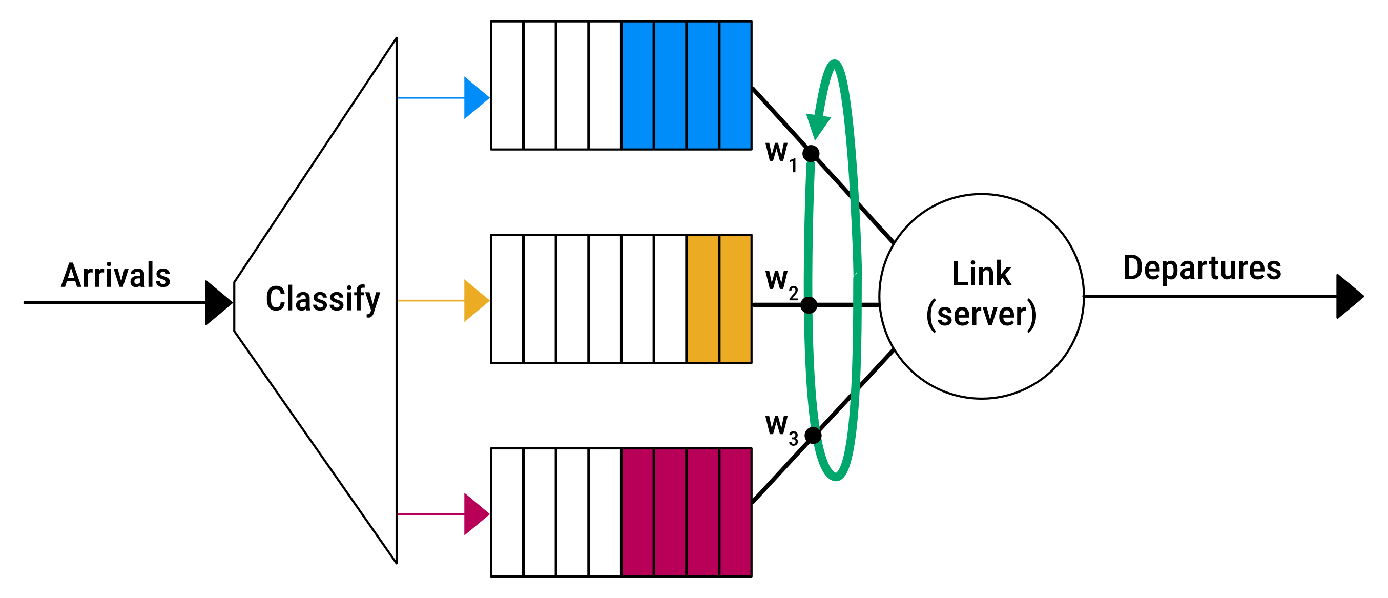
Round robin and Weighted Fair Queuing (WFQ) |
Round robin sorts packets into classes, and serves them in turn rather than by strict priority. Example: A work-conserving queuing discipline immediately moves on to the next class when it finds an empty class queue. Weighted Fair Queuing (WFQ) is a weighted version of round robin:
|
|
Net neutrality
Packet scheduling mechanisms (e.g. priority queuing and WFQ) can give different levels of service to different traffic classes.
The definition of a traffic "class" is determined by the ISP and may be based on information such as:
- port numbers (application type)
- source or destination IP addresses
This could allow an ISP to:
- prioritize certain applications or customers
- provide preferential treatment to paying companies
- block traffic from specific sources
Policies and laws that determine what an ISP is allowed to do can vary by country.
Net neutrality is the principle that all Internet traffic should be treated equally by ISPs.
 Joint
Joint