IPv4
At the network layer, the Internet Protocol (IP) is responsible for moving packets between sending and receiving hosts.
IPv4 is the fourth version of IP.
IPv4 datagram format
| IPv4 - Internet Protocol Version 4 (32 bits) | |||||||
|---|---|---|---|---|---|---|---|
| Offsets (starting positions) |
Octet | 0 | 1 | 2 | 3 | ||
| Octet | Bit | 4-7 | 0-3 | 8-15 | 16-18 | 19-23 | 24-31 |
| 0 | 0 | Version | Header Length | Type of Service | Total Length | ||
| 4 | 32 | 16-bit Identifier | 3-bit Flags | 13-bit Fragment Offset | |||
| 8 | 64 | Time to Live | Upper-layer protocol | Header Checksum | |||
| 12 | 96 | 32-bit Source IP Address | |||||
| 16 | 128 | 32-bit Destination IP Address | |||||
| 20 | 160 | Options (if any) | |||||
| 24+ | 192+ | Data | |||||
| Field | Description |
|---|---|
Version |
Specify the IP protocol version. |
Header length |
An IPv4 datagram can contain a variable number of options. These bits are used to determine where the payload actually begins. |
Type of service (TOS) |
Allows different types of IP datagrams to be distinguished from each other (e.g. real-time IP telephony traffic versus non-real-time FTP traffic). The specific level of service is a policy issue determined and configured by the network administrator for that router. Historically called the Type of Service (ToS) field. Modern networks interpret it as a DSCP field (6 bits) plus ECN (2 bits). |
Total Length |
Total length of the IP datagram (header plus data) in bytes. Since this field is 16 bits long, the theoretical maximum size of an IP datagram is 65,535 bytes, although datagrams are rarely larger than 1,500 bytes. |
Identifier, Flags, Fragmentation offset |
Related to IP fragmentation. IPv6 moved responsibility away from routers. Fragmentation may only be performed by the source host using the IPv6 Fragment extension header. |
Time-to-live (TTL) |
Ensures datagrams do not circulate forever (e.g. due to a routing loop). The field is decremented by one at each router hop. If the TTL reaches 0, the router must drop the datagram. |
Upper-layer protocol |
Used only when an IP datagram reaches its final destination. Indicates the transport-layer protocol number to which the data portion should be passed. For example, 6 indicates TCP and 17 indicates UDP. The protocol number plays a role analogous to the port number in a transport-layer segment: it binds the network layer to the transport layer, just as port numbers bind the transport layer to the application layer. |
Header checksum |
The checksum must be recomputed at every router because the TTL field is modified during forwarding. IP checksums only the IP header, whereas TCP/UDP checksums cover the entire segment. Error checking is performed at both the transport and network layers because IP can carry data that will not be passed to TCP/UDP. |
Source and destination IP addresses |
Contain the sender's and receiver's IP addresses. |
Options |
Optional field that allows the IP header to be extended. It complicates processing because header lengths become variable, making it harder to determine where the data field begins. Some datagrams require option processing while others do not, causing processing times to vary. For these reasons, IPv6 does not include IP options in its header. |
Data (payload) |
The encapsulated data carried by the IP datagram. |
Interfaces
A host:
- uses a single network link to send and receive IP datagrams
- the boundary between the host and the physical link is called an interface
A router:
- receives a datagram on one link and forwards it on some other link
- so it must have at least two network links
- the boundary between the router and any one of its links is also called an interface
- a router thus has multiple interfaces, one for each of its links
IP addresses
IP requires each interface to have its own globally unique IP address (except behind NAT):
- 32 bits (4 bytes)
- allows about 4 billion possible addresses (232)
- each byte is written in its decimal form (
11000001 00100000 11011000 00001001=193.32.216.9) - cannot be chosen at random because part of an interface's IP address depends on the subnet it is connected
Subnet
A subnet is a group of interfaces that can communicate without passing through a router.
E.g., 1 router (with 3 interfaces) connects 7 hosts:
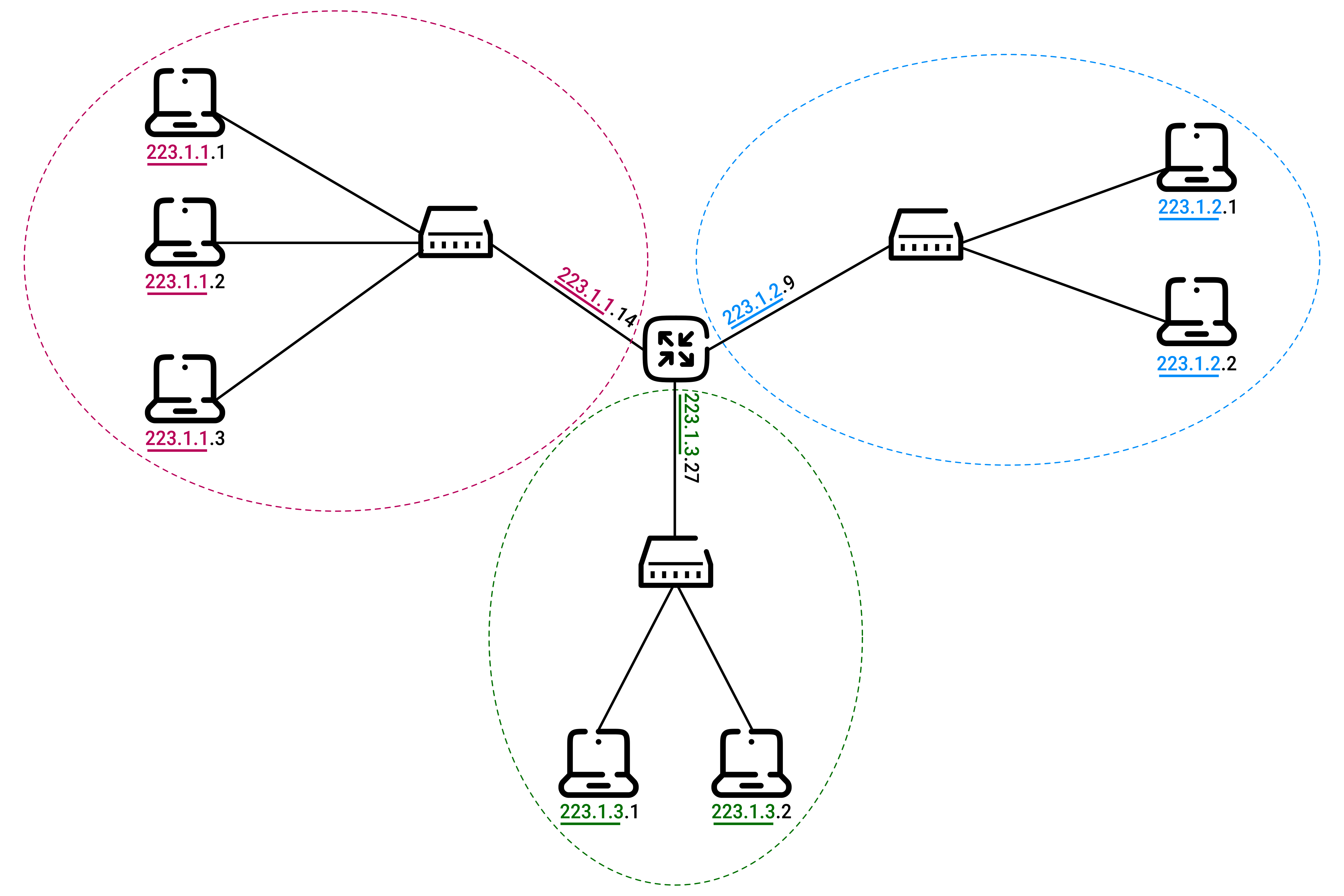
- the top-left subnet:
- all interfaces in this subnet have IP addresses of the form
223.1.1.xxx - they share the same leftmost 24 bits (the subnet prefix)
- they are connected together without any router in between (the connection is represented as an Ethernet switch)
- IP addressing assigns the address
223.1.1.0/24to this subnet where/24is the subnet mask:- the first 24 bits identify the subnet
- the remaining 8 bits identify individual interfaces within the subnet
- the
223.1.1.0/24subnet includes:- 3 host interfaces (
223.1.1.1,223.1.1.2, and223.1.1.3) - 1 router interface (
223.1.1.4) - any additional hosts attached to
223.1.1.0/24would be required to have an address of the form223.1.1.xxx
- 3 host interfaces (
- all interfaces in this subnet have IP addresses of the form
- other subnets in the diagram:
223.1.2.0/24223.1.3.0/24
A router separates different subnets and acts as a boundary between them:
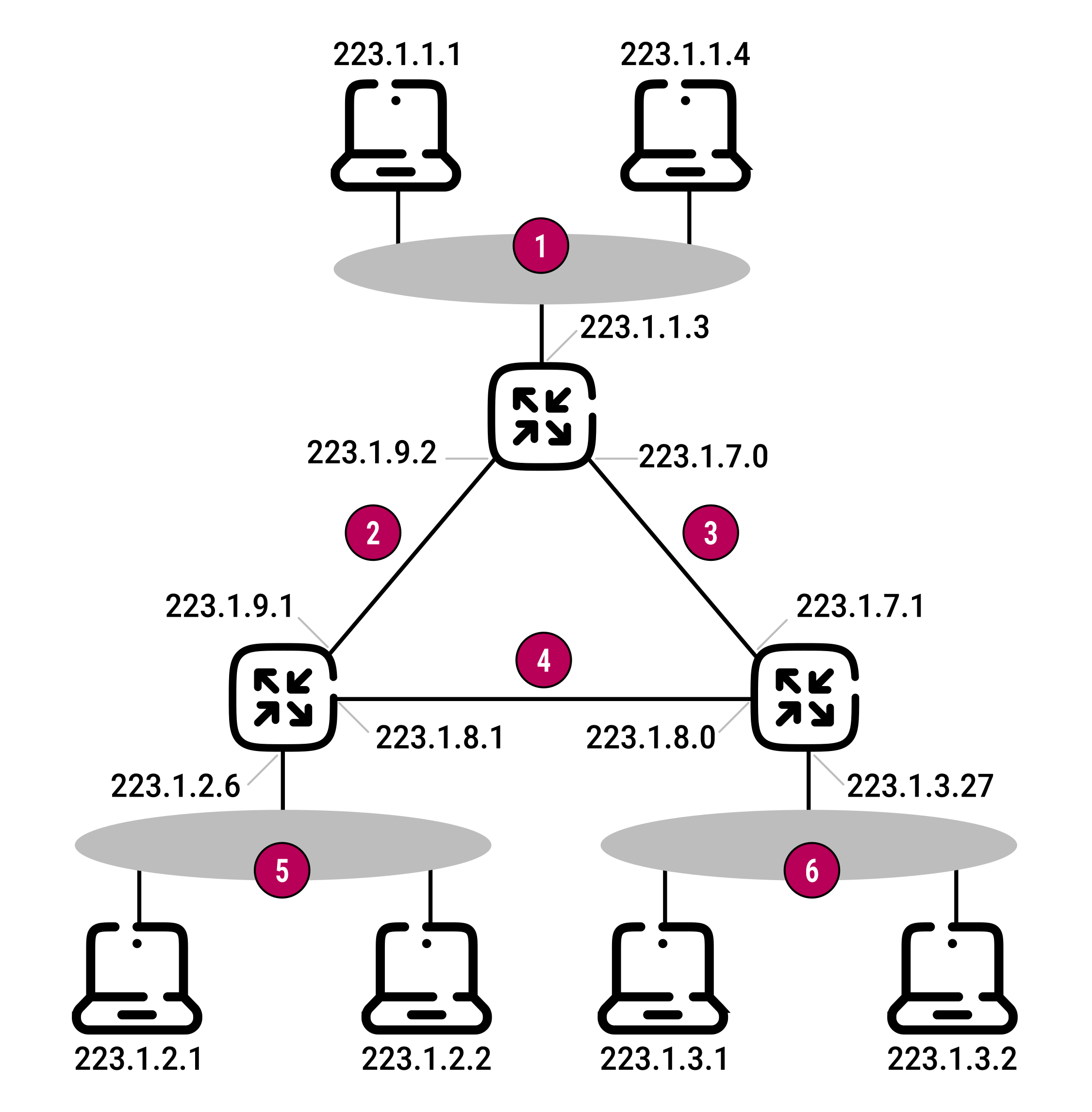
- a subnet is not restricted to group of devices on the same Ethernet network
- a subnet can also connect the interfaces between two routers
Different subnets can have very different addresses, but in practice their addresses often look similar because of how Internet addressing is structured.
The Internet's address assignment strategy
The Internet uses Classless Interdomain Routing (CIDR) (RFC 4632) to assign IP addresses:
- an IP address is a 32-bit number written as
a.b.c.d/x - where
xindicates how many bits are used for the network part of the address:- the first
xbits are the network prefix - the remaining
32 − xbits identify devices inside the network
- the first
An organization is given a block of consecutive IP addresses that all share the same prefix.
Routers outside the organization only look at the x prefix:
- this reduces the size of forwarding tables
- since a single entry
a.b.c.d/xis sufficient to forward packets to any destination within the organization
Inside the organization:
- the remaining
32 - xbits are used to distinguish between devices - there may also be smaller subnet structures within the network
Before CIDR:
- the addressing scheme was a classful addressing (RFC 1166):
- subnet portions of IP addresses were constrained to be
8,16, or24bits in length: - Class
A(/8) →2^8 = 256addresses - Class
B(/16) →2^16 = 65 536addresses - Class
C(/24) →2^24 = 16,777,216addresses
- subnet portions of IP addresses were constrained to be
- this caused problems:
- Class
Cnetworks were often too small - Class
Bnetworks were often too large
- Class
- e.g. an organization with
2,000hosts was allocated a classB(/16) subnet address:- this led to a rapid depletion of the class
Baddress space - and poor utilization of the assigned address space
- that could not be used by other organizations
- this led to a rapid depletion of the class
Broadcast address
IPv4 provides broadcast addresses that allow a packet to be delivered to all hosts on a subnet.
The special address 255.255.255.255 is the limited broadcast address (RFC 791):
- reaches all hosts on the local network link
- not forwarded by routers
- used when the sender does not know the local subnet (e.g. DHCP discovery)
Each subnet also has a directed broadcast address obtained by setting all host bits to 1:
| Subnet | Directed broadcast |
|---|---|
192.168.1.0/24 |
192.168.1.255 |
10.1.0.0/16 |
10.1.255.255 |
172.16.4.0/22 |
172.16.7.255 |
Limited broadcast is used when you don't yet know the network structure; directed broadcast is used when you already know the subnet and want to reach all hosts in it.
Directed broadcast is now rarely used and often disabled due to security concerns, with multicast preferred instead.
Obtaining a host address: DHCP
When an organization receives a block of IP addresses, it assigns them to its devices interfaces:
- routers: are manually configured, often remotely with a network management tool
- hosts: can be configured manually but are often configured using the Dynamic Host Configuration Protocol (DHCP)
DHCP automatically provides network settings to a device when it connects to a network:
- it can assign an IP address automatically:
- a device may receive the same IP address every time it connects
- or a different temporary IP address
- it allows a host to learn other network information:
- the subnet mask
- the default gateway = the address of its first-hop router
- the address of the local DNS server
Because DHCP handles these settings automatically, it is often called a plug-and-play protocol.
DHCP is a client-server protocol:
- the client is a device that has just joined the network and needs configuration information
- the server provides that information (in the simplest case, each subnet has its own DHCP server)
If there is no DHCP server on a subnet, a DHCP relay agent (usually a router) forwards requests to a DHCP server located elsewhere on the network.
When a device joins a network, DHCP assigns it an IP address through a four-step process:
| Step | Description |
|---|---|
1. DHCP server discovery |
The client needs to find a DHCP server:
|
2. DHCP server offer(s) |
Several DHCP servers can be present on the subnet:
|
3. DHCP request |
The client chooses one of the offers:
|
4. DHCP ACK |
The selected server responds with a DHCP ACK (Acknowledgment) message:
|
DHCP also provides a mechanism that allows a client to renew its lease on an IP address.
A major limitation of DHCP is that a device receives a new IP address whenever it moves to a new subnet:
- this change of IP address breaks existing TCP connections
- mobile cellular networks have a solution for this problem
Network address translation (NAT)
When a small office or home office (SOHO) sets up a local area network (LAN), all devices need IP addresses.
A common solution is Network Address Translation (NAT) (RFC 2663, RFC 3022).
A NAT-enabled router makes the entire home network appear as a single device to the Internet:
- all outgoing traffic uses the router's public IP address as the source address
- all incoming traffic is sent to that same public IP address
- devices inside the home network are hidden from the outside world
Private IPs
The devices on the local network use private IP addresses:
- three portions of the IP address space are reserved for a private network or a realm with private addresses (RFC 1918)
- e.g., subnet
10.0.0.0/24
The router gets its public IP address from the ISP's DHCP server.
The router then acts as a DHCP server and assigns private IP addresses to the computers and devices on the home network.
NAT translation table
How does a NAT router know which internal host should receive an incoming packet?
A NAT router uses a NAT translation table that maps internal IP addresses and port numbers to external port numbers.
Suppose host 10.0.0.1 requests a web page from 128.119.40.186 on port 80:
| Step | Details |
|---|---|
|
1. The host sends the datagram into the LAN |
|
|
2. The NAT router modifies the datagram |
|
|
3. The web server sends a reply |
|
|
4. The NAT router receives the reply |
|
NAT critics
Some argue that:
- port numbers are intended to identify processes, not hosts
- this can create issues for servers running on home networks:
- server applications listen on well-known ports
- in peer-to-peer systems:
- peers must accept incoming connections when acting as servers
- but how can one peer connect to another peer that is behind a NAT server?
- technical solutions to these problems include NAT traversal tools (RFC 5389)
More philosophical arguments:
- routers are meant to operate at layer 3 (the network layer) only
- NAT breaks this design principle by requiring routers to inspect and modify higher-layer information
- this violates the idea of direct end-to-end communication between hosts
 Joint
Joint