IEEE 802.11 Wi-Fi
Many wireless LAN technologies and standards were developed during the 1990s.
One family of standards became dominant: IEEE 802.11 wireless LAN (WLAN), known as Wi-Fi.
There are several 802.11 standards:
| Year (approx.) | Standard | Frequency | Maximum theoretical data rate |
|---|---|---|---|
| 1997 | 802.11 (original) | 2.4 GHz | 2 Mbps |
| 1999 | 802.11a | 5 GHz | 54 Mbps |
| 1999 | 802.11b | 2.4 GHz | 11 Mbps |
| 2003 | 802.11g | 2.4 GHz | 54 Mbps |
| 2004 | 802.11i (security amendment) | — | — |
| 2009 | 802.11n (Wi-Fi 4) | 2.4 / 5 GHz | 600 Mbps |
| 2012 | 802.11ad | 60 GHz | 7 Gbps |
| 2013 | 802.11ac (Wi-Fi 5) | 5 GHz | 6.9 Gbps |
| 2016 | 802.11ah (Wi-Fi HaLow) | Sub-1 GHz | 347 Mbps |
| 2018 | 802.11ay | 60 GHz | 20–40 Gbps |
| 2021 | 802.11ax (Wi-Fi 6) | 2.4 / 5 GHz | 9.6 Gbps |
| 2021+ | 802.11az | 2.4 / 5 / 6 GHz | — |
| 2024 | 802.11be (Wi-Fi 7) | 2.4 / 5 / 6 GHz | 46 Gbps |
| Expected late 2020s | 802.11bn (Wi-Fi 8, in development) | 2.4 / 5 / 6 GHz | Targets around 100 Gbps class |
The different standards share several characteristics:
- they share a common 802.11 MAC frame format
- they are backward compatible within overlapping frequency bands
- they use the same medium access protocol (CSMA/CA), with later amendments adding efficiency improvements (such as OFDMA)
They differ mainly at the physical layer, where devices operate in different frequency bands:
- 2.4 GHz band (≈ 2.4–2.4835 GHz):
- provides fewer non-overlapping Wi-Fi channels and is shared with many other devices (such as Bluetooth devices or microwave ovens)
- 5 GHz band (≈ 5.1–5.8 GHz):
- provides more available Wi-Fi channels and generally experiences less contention from nearby networks
- has shorter range and weaker wall penetration than 2.4 GHz signals because of higher path loss
The 802.11 architecture
The main building block of the 802.11 architecture is the basic service set (BSS) which includes:
- one or more wireless devices (stations):
- each has a unique MAC address stored in its network interface card
- one central device called an access point (AP):
- it has a unique MAC address for its wireless interface
- it connects to a switch or router, which in turn leads to the Internet
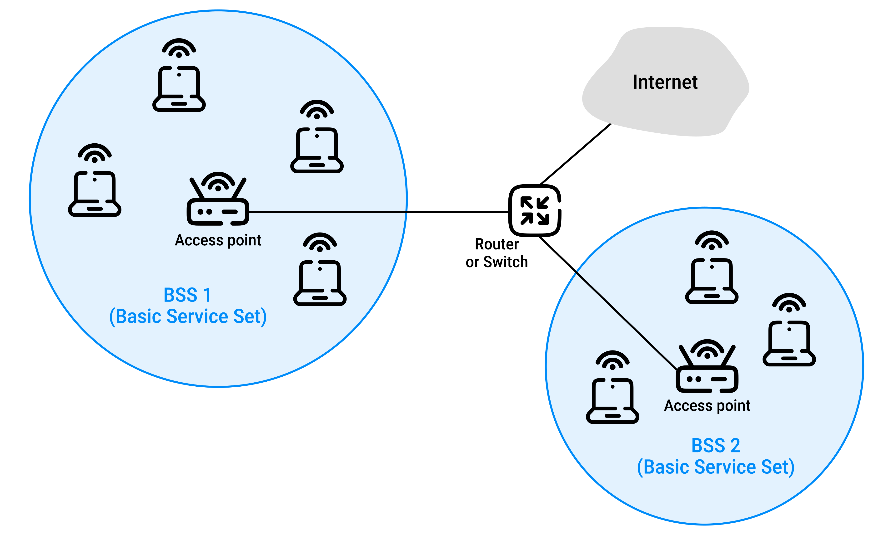
In a typical home network: there is one AP and one router, often combined into a single device.
Association (IEEE 802.11 b/g/n/ac/ax)
Before a Wi-Fi device can send or receive data, it must associate with an AP (access point).
Access Points
When setting up an AP, a network administrator assigns:
- an SSID (Service Set Identifier) (the Wi-Fi network name)
- a channel (the radio frequency the AP uses to communicate)
Wi-Fi channels
A channel is a portion of the radio spectrum used by a Wi-Fi network to transmit and receive data.
Wi-Fi operates on several radio frequency bands, including:
- 2.4 GHz: 11 channels
- 5 GHz: ≈45 channels
The 2.4 GHz band spans from 2.400 GHz to 2.4835 GHz (≈85 MHz):
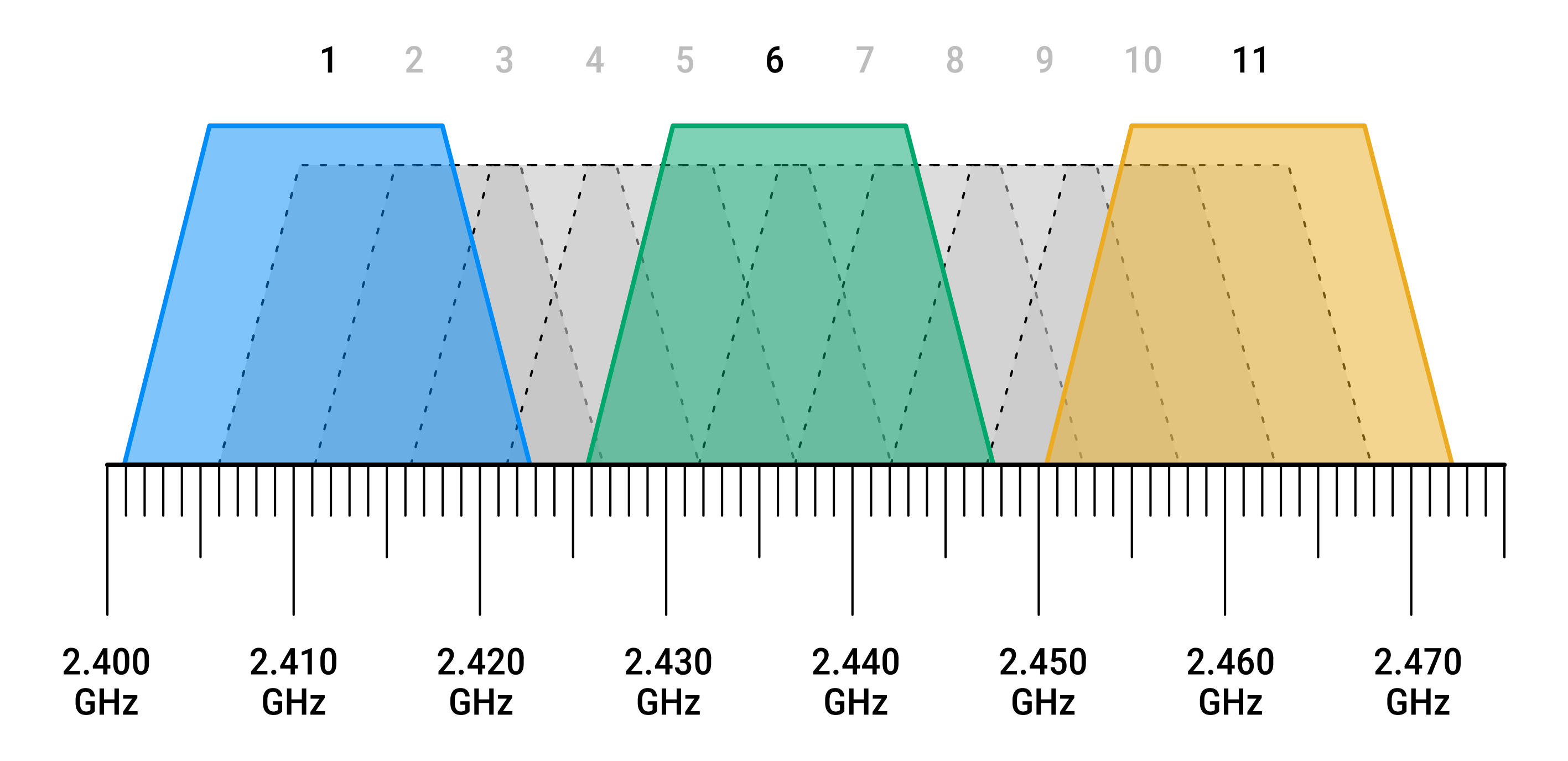
- it contains 11 partially overlapping channels
- two channels do not interfere only if they are at least 4 channels apart
- therefore, the only set of three non-overlapping channels is
1,6, and11
Wi-Fi jungle
A Wi-Fi jungle is a location where a device can detect signals from multiple APs.
For example, in a busy café, your phone might detect:
- the café's Wi-Fi
- nearby residential apartments' Wi-Fi networks
- other businesses' Wi-Fi networks
Each AP may:
- belong to a different network (IP subnet)
- use a different channel
Although many APs are available, your device can associate with only one AP at a time.
Association establishes a logical connection between the device and the AP:
- the AP sends frames only to associated devices
- the device sends all network traffic through that AP
How does a device find an AP?
Passive scanning (beacon frames):
- the 802.11 standard requires that an AP periodically send beacon frames (trame de balisage)
- every 100 milliseconds by default
- a beacon frame includes the AP's SSID and MAC address
- a device scans the available Wi-Fi channels, listening for beacon frames (this process is called passive scanning)
- after discovering nearby APs, the device chooses one for association
- the IEEE 802.11 standard does not specify how this choice is made
- some devices simply select the AP with the strongest signal, although this is not always the best choice because a stronger AP may already be heavily loaded
Active scanning:
- instead of waiting for beacon frames, a device can perform active scanning
- it broadcasts a probe request frame, and any AP within range replies with a probe response frame
Association process
After selecting an AP:
- the wireless device sends an association request frame to the AP
- the AP responds with an association response frame
The device is now associated with the AP.
Getting an IP address
Association only establishes the wireless connection.
The device then joins the IP subnet by obtaining an IP address:
- it sends a DHCP discovery message into the subnet via the AP
- after receiving an IP address, the device becomes a normal host on that IP subnet and can communicate with other hosts and the Internet
Authentication
Some Wi-Fi networks require authentication before a device is allowed to associate.
Common methods include:
- requiring a username and password
- allowing only approved MAC addresses
The AP usually forwards authentication requests to a separate authentication server using protocols such as RADIUS or DIAMETER.
The 802.11 MAC Protocol
Why is a MAC protocol needed?
After connecting to an access point (AP), multiple wireless devices may want to send data over the same wireless channel at the same time.
So a multiple access protocol is needed to prevent devices from interfering with each other.
802.11 WLANs use a random access protocol referred to as CSMA/CA (Carrier Sense Multiple Access with Collision Avoidance).
CSMA/CA follows a simple idea:
- listen before transmitting
- avoid transmitting when the channel is busy
- use a random backoff to reduce the chance of collisions
Wi-Fi cannot detect collisions
Wi-Fi was inspired by Ethernet, but it cannot use collision detection (CSMA/CD) for two main reasons:
- wireless devices cannot detect collisions while transmitting:
- a station's own transmitted signal is much stronger than any incoming signal from another station
- the receiver is overwhelmed by its own transmission, making it difficult to detect another station transmitting at the same time
- detecting another transmission underneath its own signal would require complex and costly hardware
- hidden terminal problem:
- some devices cannot hear each other because they are too far apart or blocked by obstacles
- for example:
- stations
AandCboth want to send data toB AandCcannot hear each other- both think the channel is idle and transmit simultaneously
- their frames collide at
B
- stations
Since collisions cannot be detected while transmitting, Wi-Fi focuses on avoiding them instead.
The 802.11 CSMA/CA protocol
When a station has a frame to send:
- it senses the channel
- if the channel has been idle for a Distributed Inter-Frame Space (DIFS) (in microseconds) and no backoff is pending, it transmits
- otherwise:
- it chooses a random backoff time (using binary exponential backoff)
- counts the backoff down only while the channel is idle
- pauses ("freezes") the countdown whenever the channel becomes busy
- when the backoff reaches zero, it transmits the frame
- it waits for an ACK
- if an ACK arrives, transmission succeeded
- otherwise, it retries with a larger backoff window
Why random backoff is important
Consider two stations, A and B, that both have frames to send. Both are waiting because a third station is currently transmitting.
When the third station finishes:
In Ethernet (CSMA/CD):
- both
AandBtransmit immediately, which may cause a collision - this is acceptable because Ethernet detects the collision
- both stations stop transmitting immediately after detecting the collision, wait a random time, and try again
- only a small portion of each frame is wasted
Wi-Fi (CSMA/CA):
- cannot detect collisions while transmitting, so it cannot abort a transmission once it has started
- therefore, once a station starts sending a frame, it must transmit the entire frame, even if it collides
- a collision therefore wastes the whole transmission, especially for long frames
To reduce this waste, Wi-Fi uses random backoff:
- when the channel is busy, each station chooses a random backoff value (hopefully different)
- the countdown starts only after the channel becomes idle
- the station whose counter reaches zero first transmits
- the other "losing" station hears this transmission, freezes its countdown, and waits until the channel is idle again
- the countdown then resumes, allowing the second station to transmit later
Collisions are still possible if:
- two hidden stations transmit at the same time
- two stations choose nearly identical backoff values and the first station's signal has not yet reached the second station
ACKs
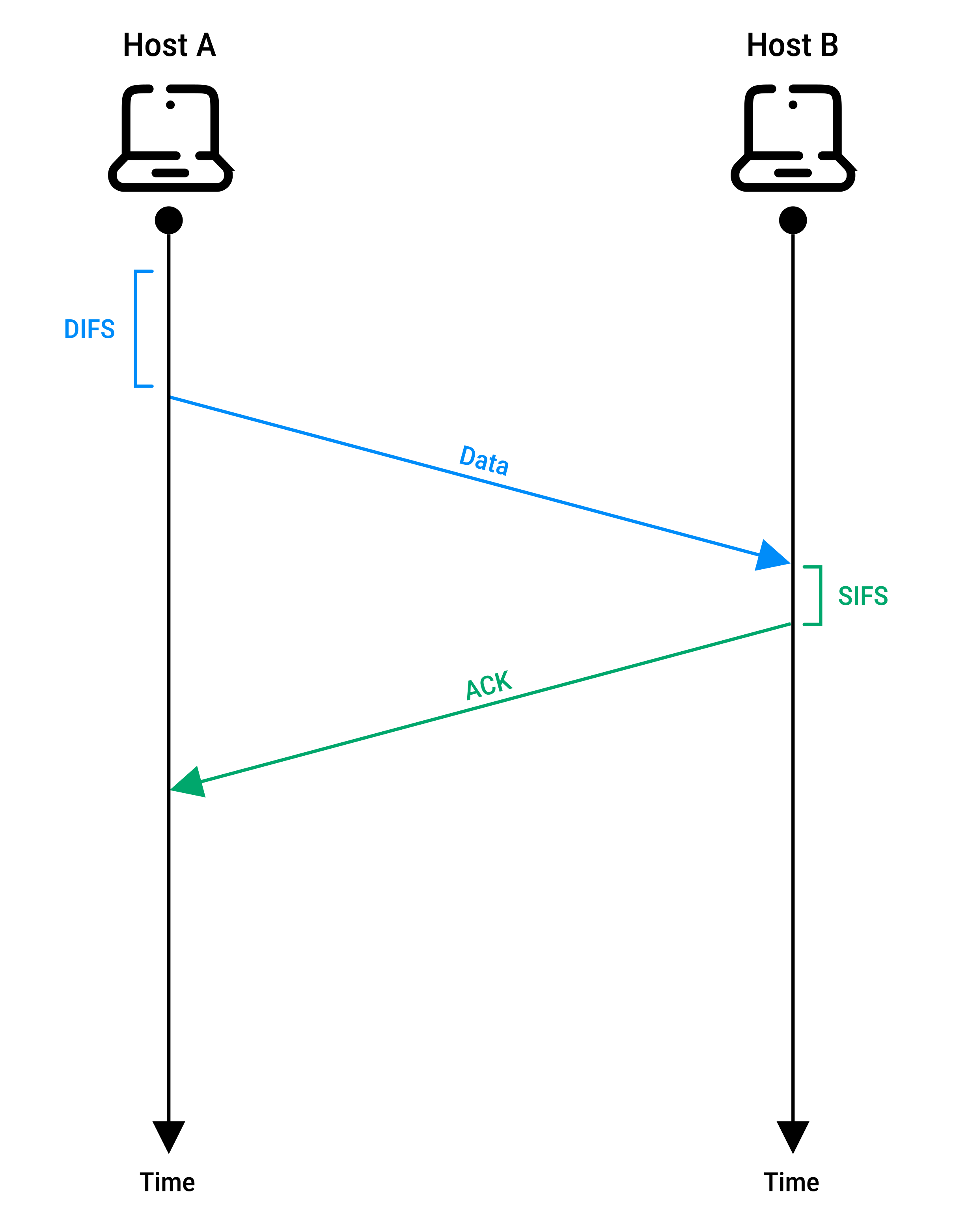
- a station sends a frame
- if the receiver passes the frame's CRC check, it waits for a Short Inter-Frame Space (SIFS)
- SIFS is shorter than DIFS, so ACKs have priority: the receiver can send the ACK before other stations are allowed to start a new transmission
- the receiver sends an ACK
- if the sender does not receive the ACK within a timeout, it assumes the frame was lost and retransmits it
- after several failed attempts, the frame is discarded
Dealing with hidden terminals: RTS and CTS
Wi-Fi (802.11) provides an optional RTS/CTS mechanism to reduce collisions caused by hidden terminals associated with the same AP.
RTS/CTS exchange:
- the sender sends an RTS (Request To Send) frame to the AP
- the RTS contains a duration field reserving enough time for the CTS, DATA frame, ACK, and required interframe spaces
- the AP replies by broadcasting a CTS (Clear To Send) frame
- the CTS:
- gives the sender permission to transmit
- tells other stations to wait until the reserved time is over
RTS/CTS reduces collisions from hidden terminals but introduces additional overhead, so it is mainly useful for large frames where avoiding retransmissions justifies the extra exchange.
In practice:
- each station can set an RTS threshold
- RTS/CTS is only used when a frame is larger than this threshold
- many devices disable RTS/CTS by default by setting the threshold above the normal maximum frame size
The IEEE 802.11 frame
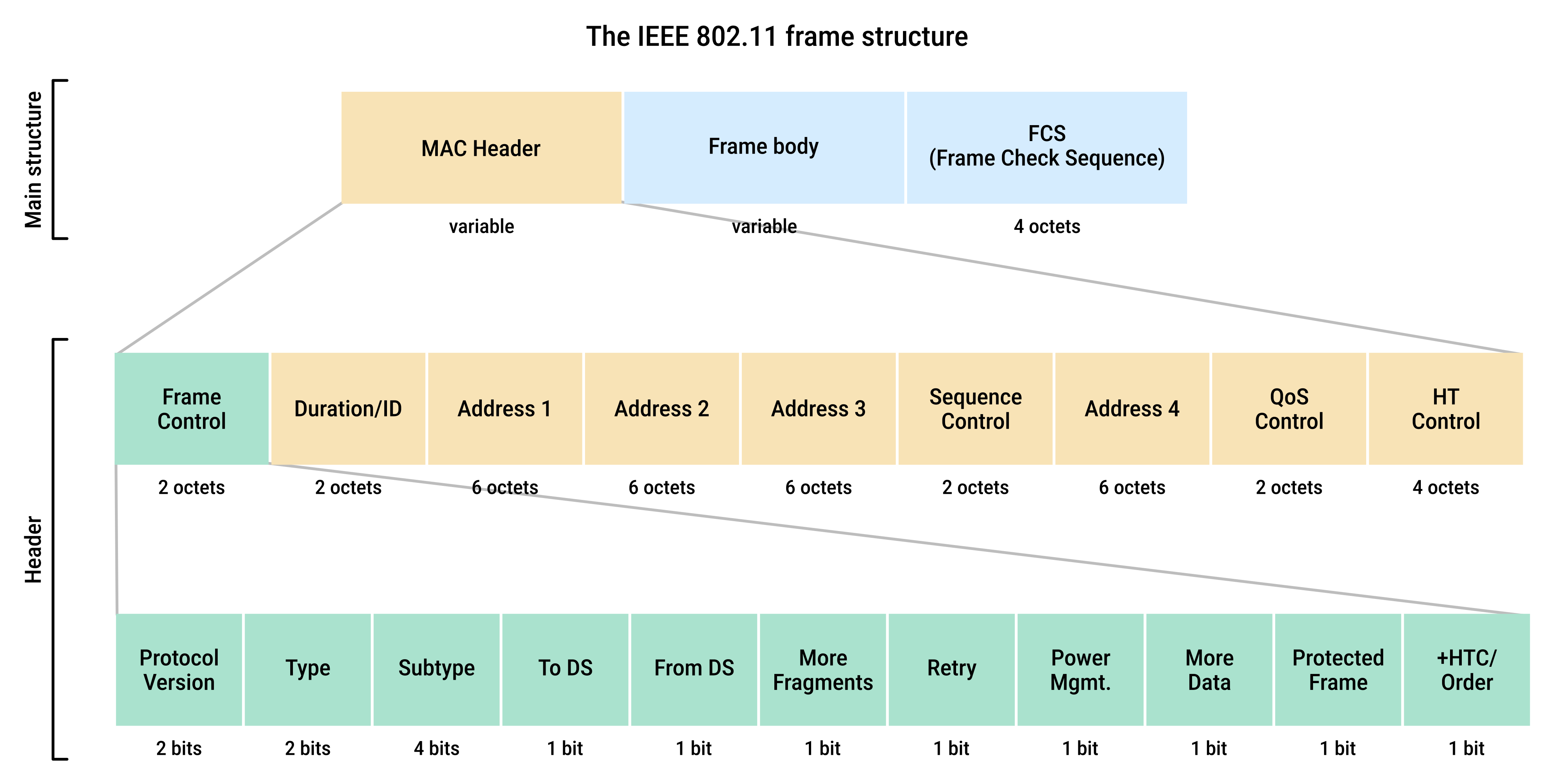
Main structure:
| Part | Description |
|---|---|
|
MAC Header |
contains control information needed to transmit and manage the frame |
|
Frame Body (Payload) |
|
|
FCS (Frame Check Sequence) |
Contains a CRC value used to detect corrupted frames. Error detection is especially important in wireless networks. |
Header:
| Field | Subfield | Description |
|---|---|---|
|
Frame Control |
Type and Subtype |
identify the kind of frame:
|
|
Protected Frame |
whether the frame body is protected using a security mechanism (such as WPA2/WPA3 encryption) |
|
|
Other Control Bits |
additional flags that control frame handling |
|
|
Address Fields (1–4) |
— |
up to 4 MAC addresses generic names ( this is because they are used differently in different situations |
|
Duration |
— |
802.11 allows a transmitting station to reserve the channel for a period of time this duration value is included in the duration field |
|
Sequence Control |
— |
because acknowledgments can get lost, a sending station may send multiple copies of a given frame sequence numbers allows the receiver to detect new or retransmitted frames |
802.11 frame addressing
Why does an IEEE 802.11 frame have up to four MAC addresses?
On an Ethernet network, a frame only needs two MAC addresses (source and destination).
In a typical Wi-Fi setup, an access point forwards frames between a wireless station and the Distribution System (DS ≈ "the upstream wired network"):
Source → (Wi-Fi) → AP → (Ethernet) → DS
802.11 therefore separates:
- the address of the devices involved at a particular hop:
TA= Transmitter AddressRA= Receiver Address
- from the original source and final destination:
SA= Source AddressDA= Destination Address
This allows 802.11 to support wireless bridging and multi-hop wireless links.
The meaning of the four generic address fields depends on the To DS and From DS bits in the frame control field:
| To DS | From DS | Address 1 | Address 2 | Address 3 | Address 4 | Notes |
|---|---|---|---|---|---|---|
| 0 | 0 | DA | SA | BSSID | — | frame stays within the wireless network (management, control, or ad hoc traffic) |
| 1 | 0 | RA (AP) | TA (station) | DA | — | wireless station → AP (frame is going toward the DS) |
| 0 | 1 | RA (station) | TA (AP) | SA | — | AP → wireless station (frame is coming from the DS) |
| 1 | 1 | RA | TA | DA | SA | AP ↔ AP (WDS, wireless bridges, mesh, repeaters) |
Four-address mode is mainly required when the frame must traverse multiple wireless links, such as wireless bridges or mesh networks.
Mobility in the same IP subnet
To extend the coverage of a wireless LAN, multiple BSSs can be deployed within the same IP subnet.
When a device moves between these BSSs, it can continue using the same IP address and maintain its existing TCP connections:
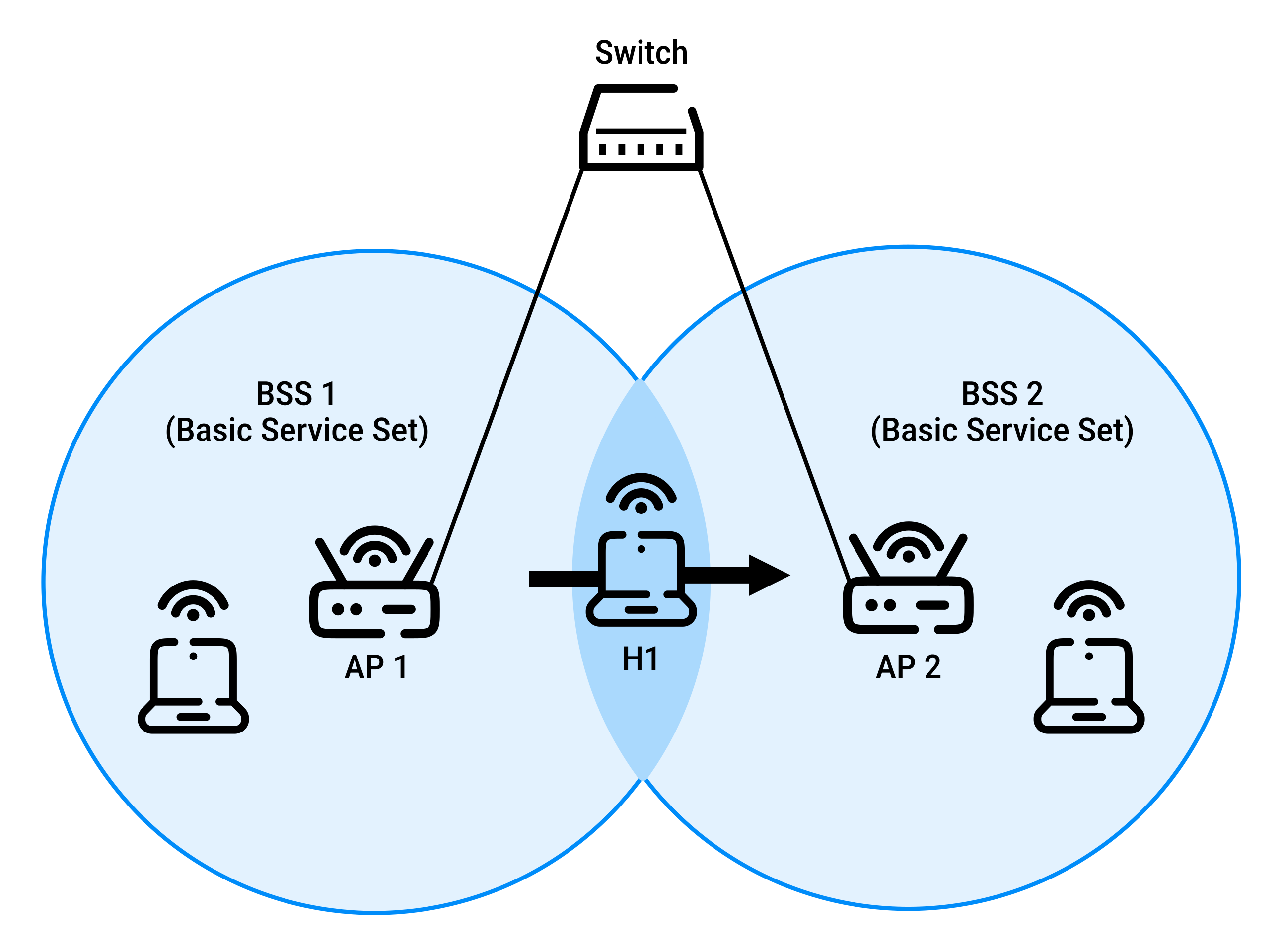
If the BSSs are connected by a switch (not a router):
- all devices, including the APs, belong to the same IP subnet
- a device can move from one BSS to another without changing its IP address
- ongoing TCP sessions continue uninterrupted
If moving to BSS2 also meant moving to a different IP subnet (for example, because the BSSs were separated by a router), the device would need a new IP address, disrupting existing TCP connections.
When H1 moves from BSS1 to BSS2:
- as
H1moves away fromAP1, the signal fromAP1becomes weaker H1scans for a stronger access point- it receives beacon frames from
AP2 H1disassociates fromAP1and associates withAP2- because both APs are in the same subnet,
H1keeps its IP address and all ongoing TCP connections
How does the switch know H1 has moved?
Before the move, the switch's forwarding table maps H1's MAC address to the port connected to AP1.
After H1 connects to AP2, the switch must update its forwarding table so that traffic is sent through AP2.
One solution is for AP2 to immediately send a broadcast Ethernet frame using H1's MAC address as the source.
When the switch receives this frame:
- it learns that
H1is now reachable throughAP2 - it updates its forwarding table
- future traffic destined for
H1is forwarded throughAP2
Case history - Location discovery: GPS and Wi-Fi positioning
A smartphone determines its location by combining two technologies:
- GPS (Global Positioning System)
- Wi-Fi positioning
GPS
GPS is a network of about 30 active satellites operated by the U.S. government and freely available to anyone with a GPS receiver.
Each satellite:
- knows its position very precisely using synchronized atomic clocks
- continuously broadcasts its current time and location
If a smartphone receives signals from at least four satellites, it can estimate its own position using trilateration.
However, GPS accuracy decreases when:
- buildings, tunnels, or other obstacles block satellite signals
- radio interference affects GPS reception
Wi-Fi positioning
Smartphones can also estimate their location using nearby Wi-Fi networks.
Companies such as Google, Apple, and Microsoft maintain databases containing millions of Wi-Fi access points and their estimated locations.
For example, an Android phone:
- detects nearby Wi-Fi access points and measures their signal strengths
- continually sends the access points' identifiers and signal strengths to Google's location service
- includes its GPS location when GPS is available
Google combines the known locations of nearby Wi-Fi access points, their signal strengths, and GPS data (when available) to produce a more accurate location estimate, which is then used by location-based apps.
How the Wi-Fi database is built
Google and other providers continually update their Wi-Fi databases using data contributed by users' smartphones.
When a phone has an accurate GPS location, it can report:
- its GPS coordinates
- nearby Wi-Fi or cellular networks
- the networks' identifiers (SSID and MAC address)
- signal strengths
By combining this information from many devices, Google can estimate and continually update the locations of Wi-Fi access points and cellular towers.
Thus:
- Wi-Fi access points help smartphones determine their locations
- Smartphones, in turn, help improve the estimated locations of Wi-Fi access points
Advanced features in 802.11
The following features are not fully specified by the 802.11 standard.
Instead, the standard defines the mechanisms needed to support them, allowing vendors to implement them using their own approaches.
802.11 rate adaptation
Some 802.11 implementations automatically adjust their transmission rate based on channel conditions.
A common approach is:
- if 2 consecutive frames are not acknowledged (ACKs), reduce the transmission rate to the next lower level
- if 10 consecutive frames are acknowledged, or enough time passes without problems, increase the transmission rate to the next higher level
This mechanism follows the same "probing" philosophy as TCP congestion control:
- increase the rate when conditions are good
- reduce the rate when transmission problems occur (for example, missing ACKs)
Power management
Power management allows Wi-Fi devices to save energy by entering sleep mode when they are not active.
The process works as follows:
- the device tells the access point (AP) it is going to sleep by setting the Power Management bit to
1in an 802.11 frame - the AP stores (buffers) frames destined for the sleeping device instead of sending them immediately
- the device wakes up (in about 250 microseconds) just before the AP sends its next beacon frame (usually every 100 ms)
- the beacon tells the device whether the AP has buffered data:
- if no data is waiting, the device goes back to sleep
- if data is waiting, the device requests the buffered frames, and the AP sends them
Because waking up takes very little time, a device with no data to send or receive can remain asleep for about 99% of the time, significantly reducing energy consumption.
 Joint
Joint